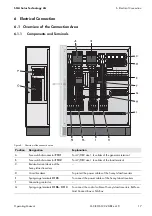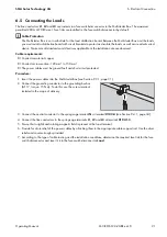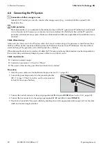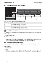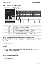
6 Electrical Connection
SMA Solar Technology AG
18
MC-BOX-12-3-20-BE-en-10
Operating Manual
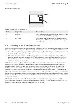
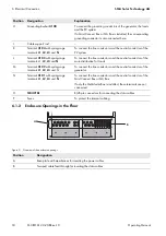
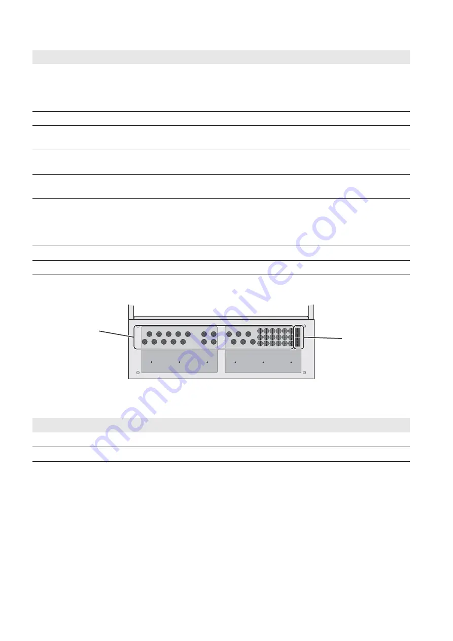
6.1.2 Enclosure Openings in the Floor
Figure 9: Overview of the enclosure openings
H
Grounding busbar
X100
To connect the grounding conductors of the generator, the loads
and the PV system
If a Grid Connect Box or NA Box is installed, the corresponding
grounding conductor is also connected here.
I
Cable support rail
–
K
Terminal
X104
with spring-cage
terminals
L1
,
L2
,
L3
and
N
To connect the line conductors and the neutral conductor of the
PV system
L
Terminal
X103
with spring-cage
terminals L1,
L2
,
L3
and
N
To connect the line conductors and the neutral conductor of the
main distribution for loads
M
Terminal
X102
with spring-cage
terminals
L1
,
L2
,
L3
and N
To connect the line conductors and the neutral conductor of the
generator
N
Terminal
X101
with spring-cage
terminals
L1
,
L2
,
L3
and
N
To connect the line conductors and the neutral conductor of the
Grid Connect Box or NA Box
If only the Multicluster Box is installed, these terminals are not
connected.
O
SIBUCTRL
RJ45 pin connectors for connecting the data cables
P
Fuses
To protect the internal cabling
Position
Designation
A
Base plate with membranes for inserting the power cables
B
Two-part cable feed-through for inserting the data cables
Position Designation
Explanation
B
A

