6 Electrical Connection
SMA Solar Technology AG
24
MC-BOX-12-3-20-BE-en-10
Operating Manual
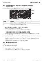
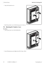
6.9 Connecting the Control Cables
6.9.1 Assignment of Spring-Cage Terminals
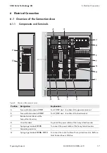
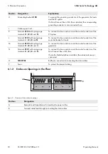
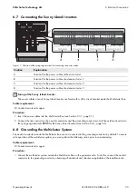
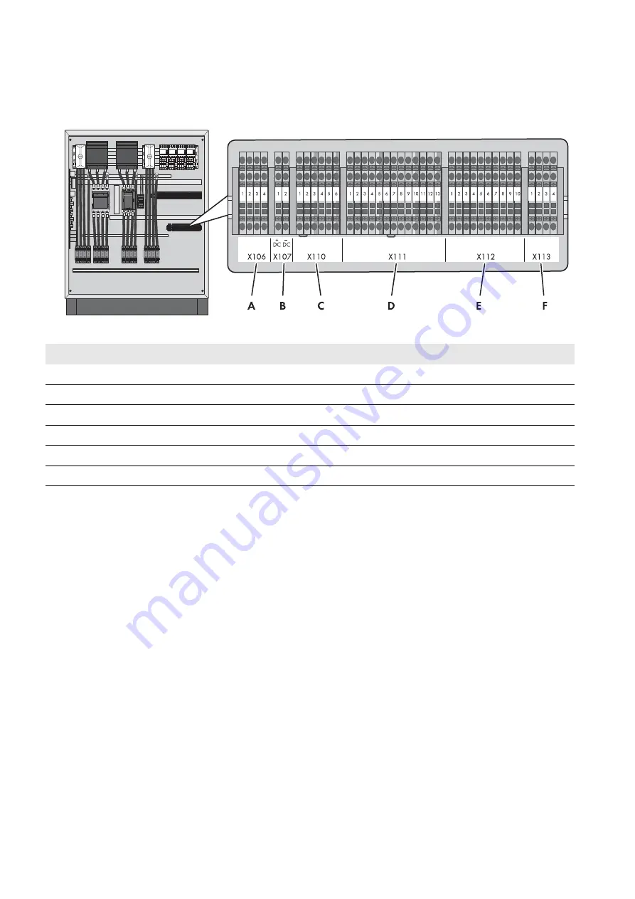
Figure 12: Overview of spring-cage terminals for connecting the control cables
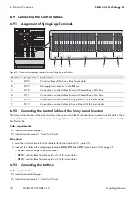
6.9.2 Connecting the Control Cables of the Sunny Island Inverters
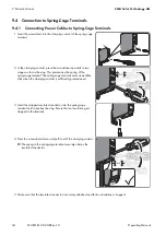
The Sunny Island inverters of the main cluster must be connected to the Multicluster Box via several control cables. These
control cables transmit measurement and control signals between the Sunny Island inverters of the main cluster and the
Multicluster Box.
Cable requirements:
Conductor material: copper
Conductor cross-section: 1.5 mm² to 2.5 mm²
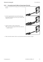
Procedure:
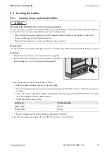
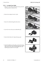
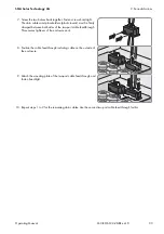
1. Insert the control cables into the Multicluster Box (see Section 9.3.1, page 31).
2. Connect the cables to the spring-cage terminals
X106
,
X112
and
X113
•
X106
: control voltage of the main cluster
•
X112
: control cables from Sunny Island 1 of the main cluster
•
X113
: control cables from Sunny Island 2 of the main cluster
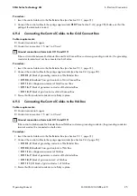
6.9.3 Connecting the BatFuse
Cable requirements:
Conductor material: copper
Conductor cross-section: 1.5 mm² to 2.5 mm²
Position
Designation Explanation
A
X106
Control voltage of the Sunny Island main cluster
B
X107
DC supply for connection to the BatFuse
C
X110
Connection of control cables from Grid Connect Box or NA Box
D
X111
Connection of control cables from Grid Connect Box or NA Box
E
X112
Connection of control cables to Sunny Island 1 of the main cluster
F
X113
Connection of control cables to Sunny Island 2 of the main cluster


