
6 Electrical Connection
SMA Solar Technology AG
26
MC-BOX-12-3-20-BE-en-10
Operating Manual
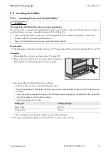
6.10 Connecting the Data Cables for Measurement Signals and
Communication
The data cables for measurement signals and communication are connected on the
SIBUCTRL
.
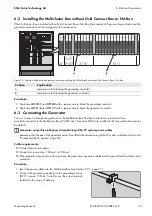
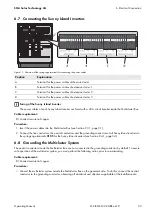
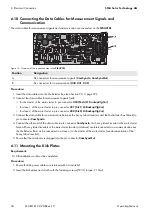
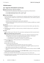
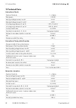
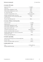
Figure 13: Overview of the connection area in the
SIBUCTRL
Procedure:
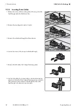
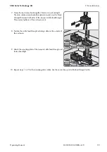
1. Insert the data cables into the Multicluster Box (see Section 9.3.2, page 32).
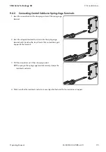
2. Connect the data cables for measurement signals (red):
• for the master of the main cluster to pin connector
X30 (Mstr/L1 BackupVtgCur)
• for slave 1 of the main cluster to pin connector
X31 (Slv1/L2 BackupVtgCur)
• for slave 2 of the main cluster to pin connector
X32 (Slv2/L3 BackupVtgCur)
3. Connect the data cable for communication between the Sunny Island inverters and the Multicluster Box (black) to
pin connector
ComSyncIn
.
4. Connect the other end of the data cable to pin connector
ComSyncIn
of a Sunny Island inverter in the main cluster.
Since all Sunny Island inverters of the main cluster (master and slaves) are interconnected via a communication bus,
the Multicluster Box can be connected to a slave or to the master of the main cluster (see documentation of the
Sunny Island inverter).
5. Ensure that the terminator is plugged into the pin connector
ComSyncOut
.
6.11 Mounting the Kick Plates
Requirement:
All installation work must be completed.
Procedure:
1. Ensure that the power cables are retained with a strain relief.
2. Insert the kick plates and attach with the fastening screws (TX 30, torque: 21 Nm).
Position
Designation
A
Pin connectors for measurement signals (
ComSyncIn
,
ComSyncOut
)
B
Pin connectors for communication (
X30
,
X31
,
X32
)