3 System Planning – Mechanical
The aim of this section is to provide general information
for planning the mechanical installation of the MLX
inverter, including mounting and cable specifications.
3.1 Unpacking
Contents:
•
Inverter
•
Mounting plate
•
Accessories bag, containing:
•
6 wall plugs 8 x 50 mm
•
6 mounting screws 6 x 60 mm
•
1 M25 cable gland with sealing
grummet for Ethernet cables
•
2 conduit brackets (2 inches - only for
UL version)
•
1 equipment grounding bolt 6 x 12 mm
•
Installation guide, booklet format
•
Quick guide, poster format
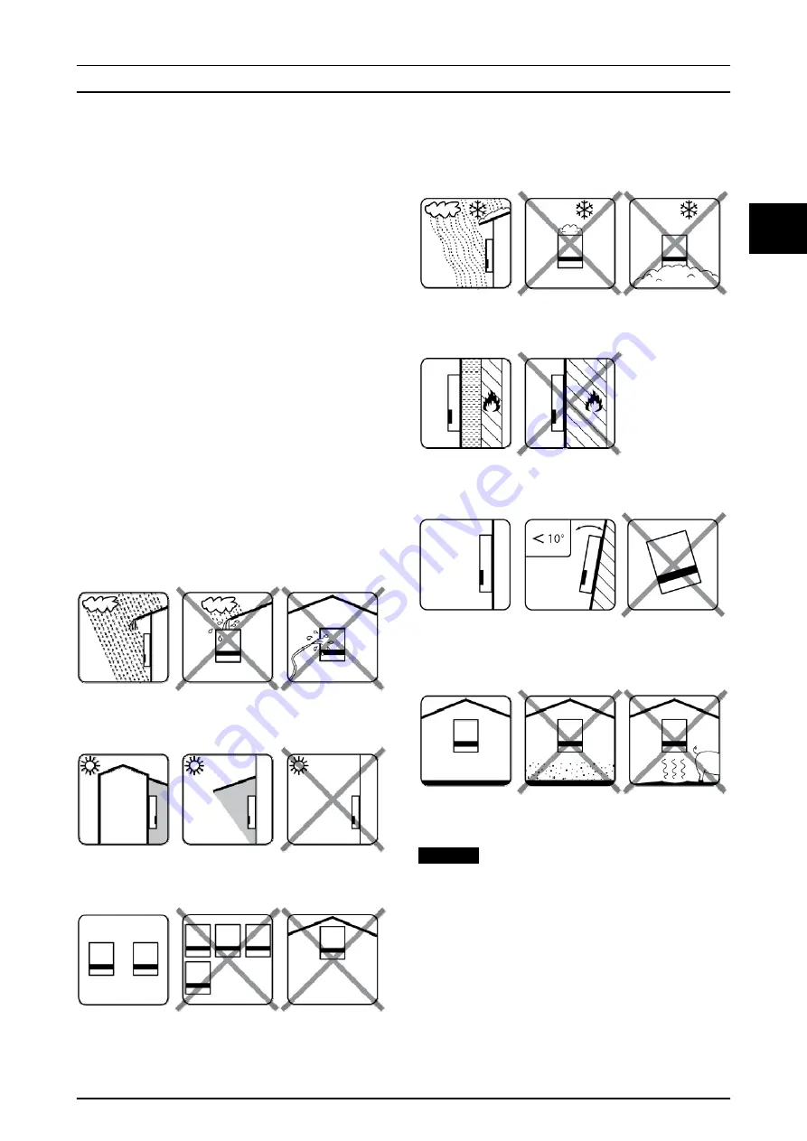
3.2 Installation
Illustration 3.1 Avoid Constant Stream of Water
Illustration 3.2 Avoid Direct Sunlight
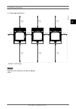
Illustration 3.3 Ensure Adequate Air Flow
Illustration 3.4 Ensure Adequate Air Flow
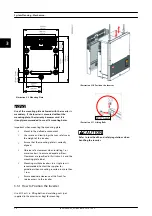
Illustration 3.5 Mount on Non-flammable Surface
Illustration 3.6 Mount Upright on Vertical Surface. Tilt of up to
10 degrees is permitted
Illustration 3.7 Prevent Dust and Ammonia Gases
NOTICE
When planning the installation site, ensure that inverter
product and warning labels remain visible. For details,
refer to
System Planning – Mechanica...
L00410648-02_02 / Rev. date: 2014-10-03
15
3
3

