6.6 Ethernet
Connections
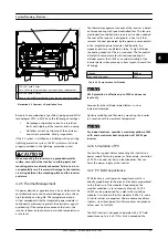
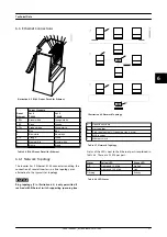
Illustration 6.2 RJ-45 Pinout Detail for Ethernet
Pinout
Ethernet
Colour Standard
Cat 5
T-568A
Cat 5
T-568B
1. RX+
Green/white
Orange/white
2. RX
Green
Orange
3. TX+
Orange/white
Green/white
4.
Blue
Blue
5.
Blue/white
Blue/white
6. TX-
Orange
Green
7.
Brown/white
Brown/white
8.
Brown
Brown
Table 6.6 RJ-45 Pinout Detail for Ethernet
6.6.1 Network Topology
The inverter has 2 Ethernet RJ-45 connectors enabling the
connection of several inverters in a line topology as an
alternative to the typical star topology.
NOTICE
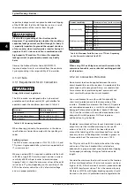
Ring topology (C in
) is only permitted if
realised with Ethernet switch supporting spanning tree.
Illustration 6.3 Network Topology
A
Linear daisy chain
B
Star topology
C
Ring topology (only if spanning tree is used)
1
MLX inverter
2
Ethernet switch
Table 6.7 Network Topology
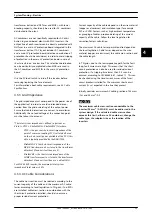
Status of the LEDs next to the Ethernet port is explained in
. There are 2 LEDs per port.
Status
Yellow LED
Green LED
Off
Link speed 10 Mbit
No link
On
Link speed 100 Mbit
Link
Flashing
-
Activity
Table 6.8 LED Status
Technical Data
L00410648-02_02 / Rev. date: 2014-10-03
31
6
6

