inverter will remain in fail safe mode until power has been
absent for a minimum of 10 minutes, or the inverter has
been shut down completely (AC+PV).
2.4 MPP Tracker and Derating
2.4.1 MPP Tracker
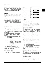
The Maximum Power Point Tracker (MPPT) is an algorithm,
which is constantly trying to maximise the output from the
PV array. The algorithm updates the PV voltage fast
enough to follow rapid changes in solar irradiance. The
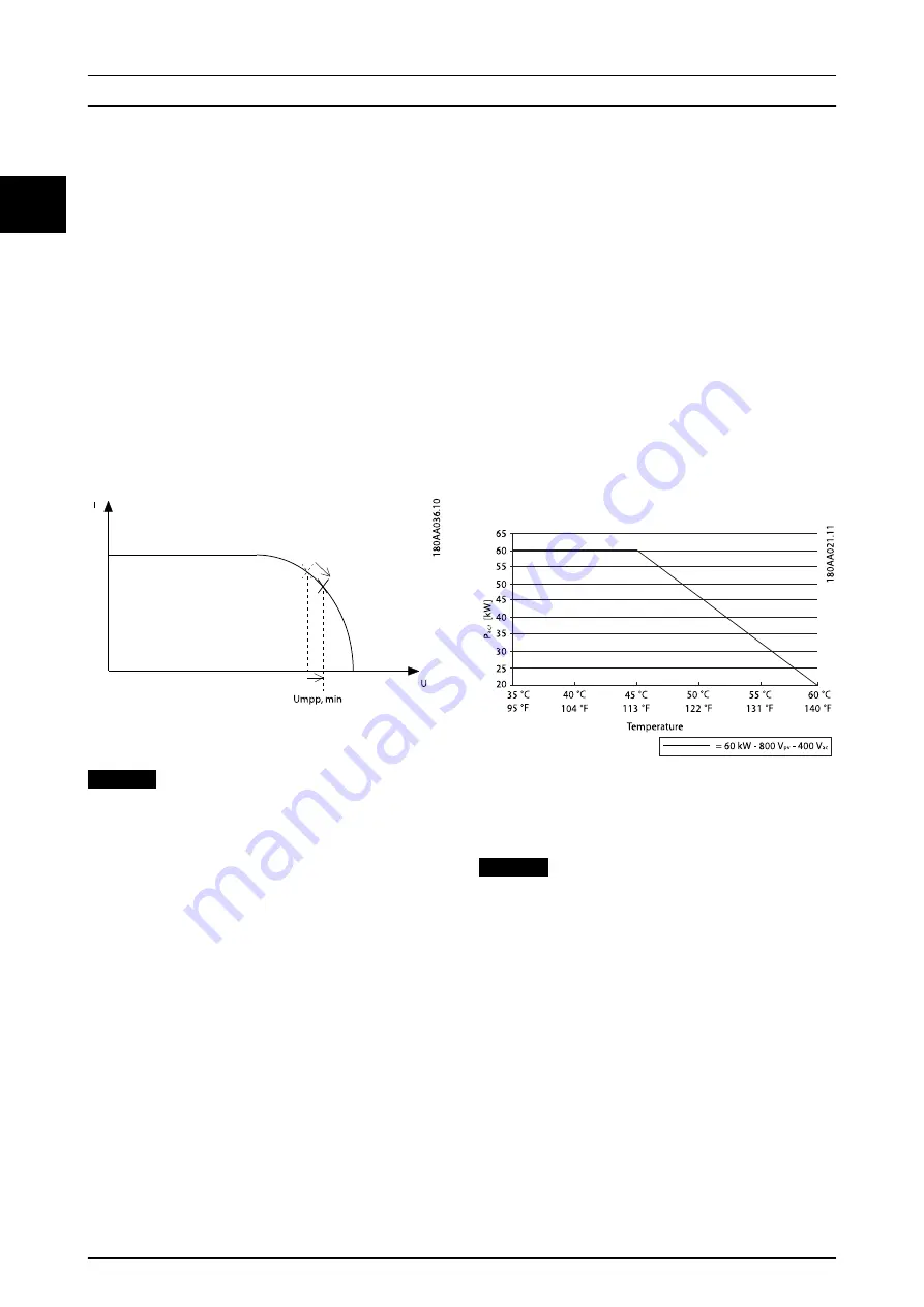
MPPT will find the maximum power point while the PV
voltage is within the specified MPP voltage range. At
voltages below the minimum MPP voltage of the inverter,
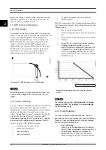
the MPPT moves away from the maximum power point
(see
) in order to maintain sufficient DC
voltage to generate the required AC grid voltage.
Illustration 2.6 MPPT Behaviour at Low MPP Voltage
NOTICE
Due to the boosterless design of the MLX inverter, the
minimum MPP voltage varies with the actual AC grid
voltage.
2.4.2 Inverter Derating
In certain situations, the MPPT purposely moves away from
the maximum power point. This behaviour is called
derating and is a means of protecting the inverter against
overload or a reduction of output power in order to
support the grid. Reactive power (supporting the grid) has
priority when the derate function is reducing the AC
output power, meaning that first active power is reduced
to zero where after reactive power is reduced. The MLX
system is derating in the following situations:
•
Exceeding max AC power rating
•
Internal over temperature
•
Grid over voltage
•
Grid over frequency
•
AC power limitation by setting or external
command (PLA)
Each MLX inverter limits the AC output power according to
the actual power reference, which will be the lowest of the
following values:
•
Max AC power rating (60 kVA)
•
Fixed active/reactive power limit set by grid code
file
•
Active/reactive power reference from the Inverter
Manager
•
Power limit from internal temperature derating.
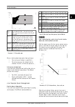
Derating due to temperature is a sign of
excessive ambient temperature, a dirty heat sink,
a blocked fan or similar. Refer to the
MLX Instal-
lation Guide
regarding maintenance. The values
shown in
are measured at nominal
conditions cos(φ) = 1
Illustration 2.7 Derating as Function of Internal Overtem-
perature
NOTICE
The inverter can use the entire admissable DC voltage
range up to 1000 V for derating. It is not restricted to
the MPP voltage range.
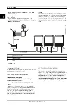
2.4.3 Power Reference
The power reference for the individual MLX inverter is
generated by the Inverter Manager based on the following
functions. They are all deployed in the Inverter Manager
and thus calculated on plant level.
•
Grid Overvoltage
When the grid voltage exceeds a DNO-defined
limit U1, the inverter derates the output power. If
the grid voltage increases and exceeds the
defined limit 10 min mean (U2), the inverter
ceases to energise the grid, in order to maintain
Inverter Overview
10
L00410648-02_02 / Rev. date: 2014-10-03
2
2


