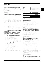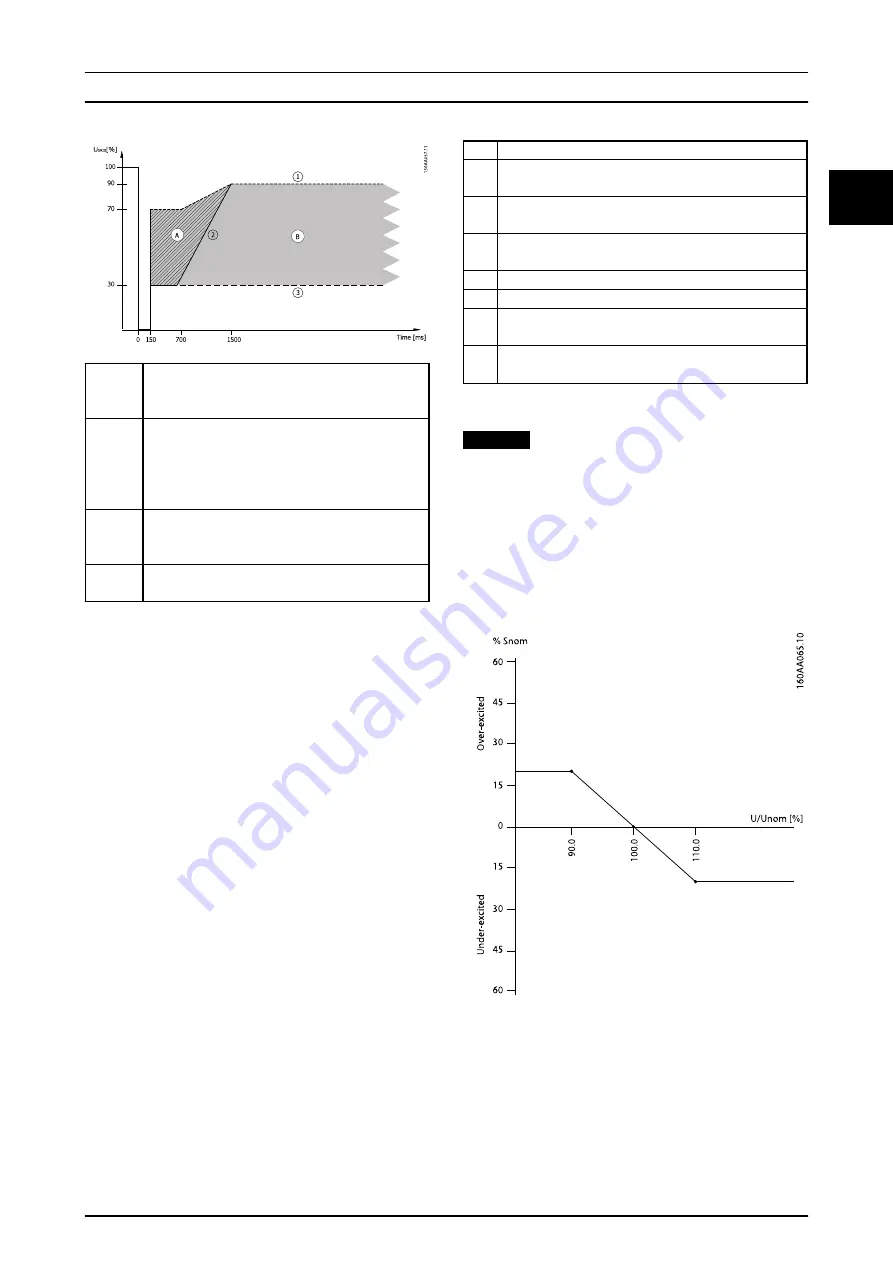
Above
line 1
For voltages above line 1, the inverter must not
under any circumstances disconnect from the grid
during FRT.
Area A
The inverter must not disconnect from grid for
voltages below line 1 and left of line 2. In some
cases, the DNO permits a short-duration discon-
nection, in which case the inverter must be back on
grid within 2 s.
Area B
Right of line 2, a short-duration disconnection from
grid is always permitted. The reconnect time and
power gradient can be negotiated with the DNO.
Below
line 3
Below line 3 there is no requirement to remain
connected to grid.
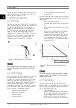
Illustration 2.12 German Example
When a short-duration disconnection from grid occurs:
•
The inverter must be back on grid after 2 s
•
The active power must be ramped back at a
maximum rate of 10% of nominal power per s
Active power management
The inverter can support the local grid by either static or
dynamic limit of the plant output power. The different
methods of control are:
•
Fixed Pref – maximum active power limit
•
Power Level Adjustment (PLA) – remotely
controlled maximum active power limit (requires
I/O box)
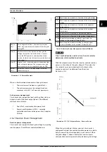
2.6.2 Reactive Power Management
Reactive power management
The inverter can support the local grid voltage by injecting
reactive power. The different control methods are:
Q(U)
Reactive power injected as a function of the grid voltage.
Q(P)
Reactive power injected as a function of the active output
power.
Q(S)
Reactive power injected as a function of the apparent
output power.
Q(T)
Reactive power injected as a function of the ambient
temperature.
PF(P) Power factor as a function of active output power.
PF(T) Power factor as a function of the ambient temperature.
PFext Power factor according to external signal either via
Modbus or the external I/O box (RS-485).
Qext Reactive power injected according to external signal
either via Modbus or the external I/O box (RS-485).
Table 2.2 Reactive Power Management, Control Methods
NOTICE
Only 1 method can be used at a time. A mode selector
determines which method to activate.
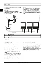
With the setpoint curve Q(U), the inverter controls reactive
power as a function of the grid voltage U. The values for
the setpoint curve are determined by the local utility
company and must be obtained from them (see
Illustration 2.13 Q(U) Setpoint Curves - Reactive Power
When the grid voltage is below nominal, the inverter is
configured to inject over-excited reactive power in order to
help increase the grid voltage back up to nominal. When
the grid voltage is above nominal, the inverter injects
under-excited reactive power to help decrease grid voltage
Inverter Overview
L00410648-02_02 / Rev. date: 2014-10-03
13
2
2


