and thus supports the grid by maintaining a more stable
and healthy voltage.
Qext. and PFext
Control of a plant’s reactive power injection can be
handled remotely with I/O box via RS-485 or via a 3
rd
-party
external signal via Modbus.
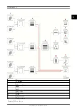
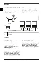
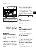
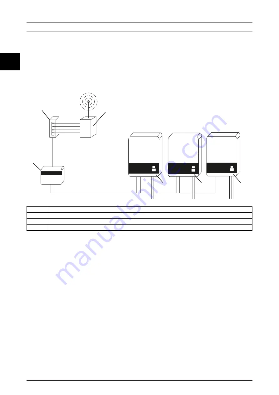
I/O box
The I/O box monitors the relay state of the Ripple control
receiver (supplied by the DNO) and transmits the state to
the Inverter manager via RS-485. The Inverter Manager
translates the relay state into the corresponding PLA value
(max. plant output power) based on the grid code configu-
ration.
2
3
1
4
4
4
Ethernet
180AA037.1
RS-485
1
Ripple Control Receiver
2
I/O Box
3
Inverter Manager
4
MLX
Illustration 2.14
External signal (3
rd
party)
Modbus SunSpec control profile can be used to control the
reactive power injected by the plant.
2.6.3 Active Power Management
Apparent power management
The inverter can support the local grid by setting a
maximum apparent power limit.
•
Fixed Sref – maximum apparent power limit
Fallback
The inverters in the inverter network are controlled by a
Qref and Pref from the Inverter Manager. If the connection
to the Inverter Manager is lost, the inverter disconnects
from grid after up to 40 seconds. If the connection is
restored within this period the inverter will not disconnect
from grid. When the connection is restored, the inverters
reconnect to grid.
2.7 Functional Safety Settings
The inverter is designed for international use and it can
handle a wide range of requirements related to functional
safety and grid behaviour. Parameters for functional safety
are predefined and do not require any alteration during
installation. However, some grid code parameters may
require alterations during installation to allow optimisation
of the local grid. Contact SMA for a custom grid code.
Inverter Overview
14
L00410648-02_02 / Rev. date: 2014-10-03
2
2


