•
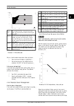
Insufficient number of modules per string
•
High grid voltage
In general, the yield losses are minor for 400 V
ac
grids.
Yield losses can be minimised for 480 V
ac
grids by:
•
Increasing the number of modules per string
•
Reducing the grid voltage seen by the inverters
Grid voltage can be reduced by:
-
modifying the tap changer position in
the transformer station
-
moving the inverters to another location
-
modifying the AC cable sections
If the previous actions are insufficient for a particular
project to minimise the yield losses due to MPP range at a
low level, an auto-transformer 480–400 V can be installed
in order to reduce the grid voltage.
NOTICE
SMA can support you in the analysis of the yield losses
due to MPP range for your particular project and in the
selection of the best technical approach.
4.2.1.3 Short-circuit Current
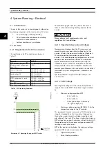
The short-circuit current (Isc) must not exceed the absolute
maximum that the inverter is able to withstand. Check the
specification of the short-circuit current at the highest PV
module operating temperature and the highest irradiance
level expected. 125% of the module Isc at STC is used per
string for the calculation, following the recommendations
of the NEC and other regulations. This implies no more
than 14 strings per inverter, for standard 60-cells c-Si
modules.
4.2.1.4 MPP Current
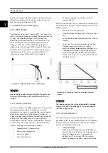
The MLX inverter is able to provide full AC power even at
its lower MPP range threshold. If the MPP current exceeds
110 A (due to high irradiance conditions or large number
of strings per inverter), the inverter does not trip but shifts
the operation point, resulting in some yield losses. In
addition, the inverter limits the power intake by shifting
the MPP when surplus PV power is available. For further
information about PV over-sizing and related
consequences, see
4.2.2 Determining Sizing Factor for PV
4.2.1.5 PV to Earth Resistance
Monitoring of the PV to earth resistance is implemented
for all grid codes. Supplying energy to the grid with too
low resistance could be harmful to the inverter and/or the
PV modules. PV modules designed according to the
IEC61215 standard are only tested to a specific resistance
of minimum 40 MΩ*m
2
. Therefore, for an 84 kWp power
plant with a 14% PV module efficiency, the total area of
the modules yields 600 m
2
. This yields a minimum
resistance of 40 MΩ*m
2
/600 m
2
= 66.67 kΩ. The PV design
must be within the required limit of the applied grid code.
See
4.2.1.6 Earthing
It is not possible to earth any of the terminals of the PV
arrays. However, it can be compulsory to earth all
conductive materials, for example, the mounting system, to
comply with the general codes for electrical installations. In
addition, the PE terminal of the inverter must be always
connected to earth.
CAUTION
It can be harmful to humans if not properly grounded.
4.2.1.7 Parallel Connection of PV Arrays
The MLX inverter has 1 input and 1 MPPT. An external
string combiner is always required. Due to the number of
strings in parallel, fusing of the strings in the string
combiner is required. The recommendation is to place the
string combiner close to the strings. The use of only 1
cable for each pole from the PV array to the inverter
reduces the cable and installation costs.
4.2.1.8 PV Cable Dimensions and Layout
DC cabling is composed of 2 different cable segments:
•
The string cabling from the modules to the string
combiner (usually 4 mm
2
or 6 mm
2
)
•
The combined line from the string combiner to
the inverter (recommended at least 50 mm
2
(copper) or 70 mm
2
(aluminium))
The cable section must be selected for each segment
according to the current capacity of the cable and
maximum DC cable losses according to local legislation.
Current capacity of the cable depends on the material of
the wires (copper or aluminium) and the type of insulation
(for example PVC or XLPE). Factors as for example high
ambient temperature or grouping of cables produce
derating of the current capacity of the cable. Follow the
local legislation for correction factors calculation.
The maximum DC cable losses permitted also depend on
the local legislation. Note that the limit must include both
the losses in the strings and the combined line. Cable
losses depend on the material of the wires (copper or
aluminium), cross-section area and the cable length.
Take the following into account:
•
The total length for a string is defined as twice
the physical distance between the string and the
System Planning – Electrica...
L00410648-02_02 / Rev. date: 2014-10-03
21
4
4

