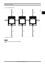
string combiner plus the length of the PV cables
included in the modules
•
The total length for the combined line is defined
as twice the physical distance between the string
combiner and the inverter
NOTICE
For the combined line, the maximum cable section
connectable to the inverter (95 mm
2
/ AWG 4/0) must be
addressed in the system design. If the calculated cable
section exceeds this limit, change the cable type, the
sub-plant size, or the location of the string combiners/
inverters.
Avoid looping the DC cables as they can act as an antenna
of radio-noise emitted by the inverter. Cables with positive
and negative polarity must be placed side by side with as
little space between them as possible. This also lowers the
induced voltage in case of lightning and reduces the risk
of damage.
4.2.2 Determining Sizing Factor for PV
Systems
When determining the PV system size factor, a specific
analysis is preferred, especially for large PV installations.
Local rules of thumb for choosing the sizing factor can be
determined, depending on local conditions, for example:
•
Local climate
•
Local legislation
•
System price level
To select the optimal configuration/sizing factor, an
investment analysis must be made. Large sizing factors
usually reduce specific investment costs (€/kWp) but could
have lower specific yield (kWh/kWp) due to derating losses
in the inverter (excessive DC power or overheating) and so,
lower income. Small sizing factors result in greater
investment costs. However, specific yield is potentially
greater due to little or no derating loss.
Installations in regions with frequent irradiation levels over
1,000 W/m
2
have lower levels of sizing factor than instal-
lations in regions with infrequent irradiance levels over
1000 W/m
2
. In particular, if high ambient temperatures are
not expected during the irradiance peaks.
A lower sizing factor must also be considered for tracking
systems, because they allow more frequent high irradiance
levels. In addition, derating due to overheating of the
inverter must be considered for tracking systems in hot
climates. This can also reduce the recommended sizing
factor further.
The MLX inverter supports different sizing factors,
depending on the number of modules per string and
number of strings per inverter.
Any configuration that observes the varying conditions for
different applications: the limits in
for short-circuit
current and open-circuit voltage will be considered as valid
and so covered by warranty.
4.2.3 Thin Film
The MLX inverter is a transformerless inverter without
booster and so the PV voltage is distributed symmetrically
to earth. Grounding of the minus pole is not allowed.
•
The use of transformerless inverters as MLX is
approved by many thin-film module manufac-
turers not requiring grounding of the minus pole
•
The MLX inverter is not compatible with thin-film
modules with a requirement of minus pole
grounding
NOTICE
It is important to get approval from the module
manufacturer before installing thin-film modules with
MLX inverters.
CAUTION
Module voltage during initial degradation can be higher
than the rated voltage in the data sheet. This must be
considered when designing the PV system, since
excessive DC voltage can damage the inverter. Module
current can also lie above the inverter current limit
during the initial degradation. In this case, the inverter
decreases the output power accordingly, resulting in
lower yield. Therefore, when designing, take inverter and
module specifications both before and after initial
degradation into consideration.
4.2.4 Internal Surge Overvoltage Protection
The MLX inverter includes high performance DIN-rail SPDs
in both AC (type II+III, according to IEC 61643-11) and DC
(type II) sides. The SPDs are easy to replace if damaged.
System Planning – Electrica...
22
L00410648-02_02 / Rev. date: 2014-10-03
4
4

