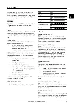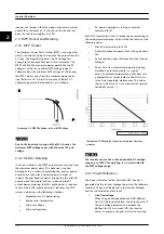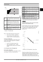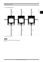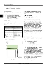
1 SPD (AC) with 3 fuses.
Fuse to far right (green) does not require any replacement.
2 SPD (DC) with 2 fuses.
Fuse in the middle (green) does not require any replacement.
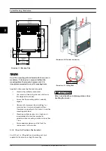
Illustration 4.2 Overview of Installation Area
Based in the combination of gas-filled spark gap and MOVs
technologies, SPDs in MLX have the following advantages:
•
No leakage or operation current: no insulation
faults and tripping of the inverter, and no aging
•
No follow current: no tripping of the upstream
overcurrent protection during surge events
If the PV system is installed on a building with an existing
lightning protection system, the PV system must also be
properly included in the lightning protection system.
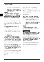
CAUTION
When mounting the inverter on a grounded metallic
surface, ensure that the inverter’s earthing point and
mounting plate are directly connected. Failure to do so
can potentially result in material damage to the inverter,
via arcing between the mounting plate and the inverter
enclosure.
4.2.5 Thermal Management
All power electronics generate excess heat, which must be
controlled and removed to avoid damage and to achieve
high reliability and long life. The temperature around
critical components like the integrated power modules is
continuously measured to protect the electronics against
overheating. If the temperature exceeds the limits, the
inverter reduces output power to maintain temperature at
a safe level.
The thermal management concept of the inverter is based
on forced cooling with speed-controlled fans. The fans are
electronically controlled and are only active when needed.
The rear of the inverter is designed as a heat sink that
removes the heat generated by the power semiconductors
in the integrated power modules. Additionally, the
magnetic parts are ventilated by force. At high altitudes,
the cooling capacity of the air is reduced. The fan control
attempts to compensate for this reduced cooling. At
altitudes greater than 1000 m, consider derating of the
inverter power when planning system layout, to avoid loss
of energy.
Altitude
2000 m
Max. load of inverter
95%
Table 4.2 Compensation for Altitude
NOTICE
PELV protection is effective up to 2000 m above sea
level only.
Account for other altitude-related factors, such as
increased irradiation.
Optimise reliability and lifetime by mounting the inverter
in a location with low ambient temperature.
NOTICE
For indoor locations, consider a maximum airflow of 640
m
3
/h and a maximum heat dissipation of 1500 W per
inverter.
4.2.6 Simulation of PV
Contact the supplier before connecting the inverter to a
power supply for testing purposes, for example, simulation
of PV. The inverter has built-in functionalities that can
harm the power supply or the inverter.
4.2.7 PV Field Capacitance
PV fields have a small parasitic capacitance, which is
directly proportional to the area and inversely proportional
to the thickness of the modules. Depending on the
weather conditions, a total capacity of about 50–150
nF/kW can be determined for a plant with crystalline
modules. For standard thin-film modules (CdTe, CIS, and a-
Si) similar values are expected. Under extreme conditions,
stainless steel sheet-based thin-film modules can produce
values near to 1 mF/kW.
The MLX inverter is designed to operate with a PV field
capacitance up to 8.8 μF. If this limit is exceeded, the
System Planning – Electrica...
L00410648-02_02 / Rev. date: 2014-10-03
23
4
4

