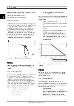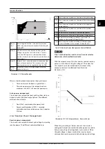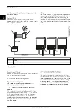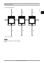
capacitive leakage current can provoke undesired tripping
of the RCMU class B of the MLX inverter, and, as a result,
the disconnection of the inverter from the grid.
WARNING
Plants with no grounding of the structure can be
dangerous. If a grounded person touches the modules, a
capacitive leakage current can flow through his body. It
is especially important to ground the support structure
of the modules when transformerless inverter having AC
ripple on the DC side are installed in combination with
high-capacity PV modules. This draws the capacitive
leakage current to ground and prevents any bodily
harm.
Observe the National Electric Code, ANSI/NFPA 70.
Input and output circuits are isolated from the enclosure.
System grounding is the responsibility of the installer.
4.3 AC
Side
4.3.1 Requirements for AC Connection
CAUTION
Always follow local regulations.
The MLX inverters are designed with a 3-phased and
protective earth (without neutral) AC grid interface for
operation under the conditions described in
Parameter
Operation range
Grid interface
3P + PE (delta or WYE)
Grid voltage, phase-phase
400 V or 480 V (+/- 10%)
Grid frequency
50 Hz or 60 Hz (+/- 10%)
Table 4.3 AC Operating Conditions
When choosing grid code, the parameters in the above
specification are limited to comply with the specific grid
codes.
Earthing systems
The MLX inverters can operate on TN-S, TN-C, TN-C-S, and
TT systems. Ungrounded delta systems are supported, but
IT systems are not.
Where an external RCD is required in addition to the built-
in RCMU, a type B RCD must be used. Consider a current
sensitivity of 600 mA per inverter to avoid nuisance
tripping.
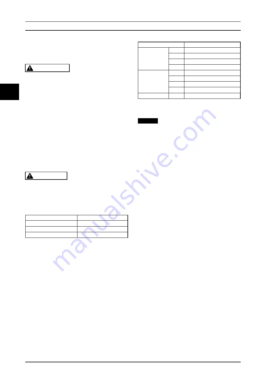
shows the maximum values of the earth
resistance in TT grids, depending on the sensitivity of the
RCD to have lower values than 50 V of contact voltage,
and so a proper protection.
Current sensitivity
Maximum value of earth resistance
Basic sensitivity
20 A
2.5 Ω
10 A
5 Ω
5 A
10 Ω
3 A
17 Ω
Medium sensitivity
1 A
50 Ω
500 mA
100 Ω
300 mA
167 Ω
100 mA
500 Ω
High sensitivity
≤ 30 mA > 500 Ω
Table 4.4 Maximum Earth Resistance in TT Grids, Depending
on the Current Sensitivity of the RCD
NOTICE
When using TN-C earthing to avoid earth currents in the
communication cable, ensure identical earthing potential
of all inverters.
4.3.2 AC Connection Protection
No consumer load can be applied between the mains
circuit breaker/fuses and the inverters. An overload of the
cable might not be recognised. Always use separate lines
for consumer loads, protected against overcurrent and
short circuit with proper fuses/circuit breakers.
Use circuit breakers/fuses with switch functionality for
short-circuit protection and safe disconnection of the
inverters. Threaded fuse elements like ‘Diazed’ (D-type) are
not considered adequate as a switch. Fuse holder can be
damaged if dismounted under load. ‘Neozed’ (D03-type,
100 A) can be installed in fuse-switch disconnection units
adequate for switch purposes. NH fuses require an
additional tool, a grip handle.
Dedicated circuit breakers/fuses for each individual inverter
output line must be installed according to the specifi-
cations in
, in which it has been taken into
account that derating of the circuit breakers/fuses can be
necessary due to self-heating when installed in groups, or
if exposed to heat. The maximum fuse size is 125 A.
For TN grids with no RCDs installed, check that the rating
and curve of the circuit breakers/fuses selected are
adequate for a proper residual current protection (tripping
fast enough), considering the type of cable and cable
length.
Consider the maximum short-circuit current in the location
of the circuit breaker/fuses. Short-circuit currents can be as
high as 60 kA, if the short-circuit current is produced inside
a 2.5 MVA transformer station. This is the reason why only
NH fuses or MCCBs, with higher breaking capacity, should
be used in the main LV protection board integrated in the
System Planning – Electrica...
24
L00410648-02_02 / Rev. date: 2014-10-03
4
4

