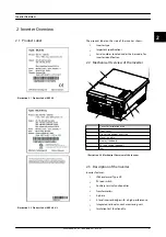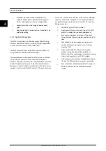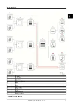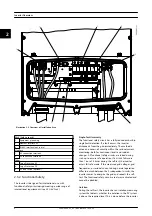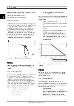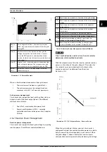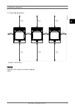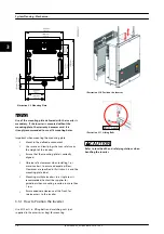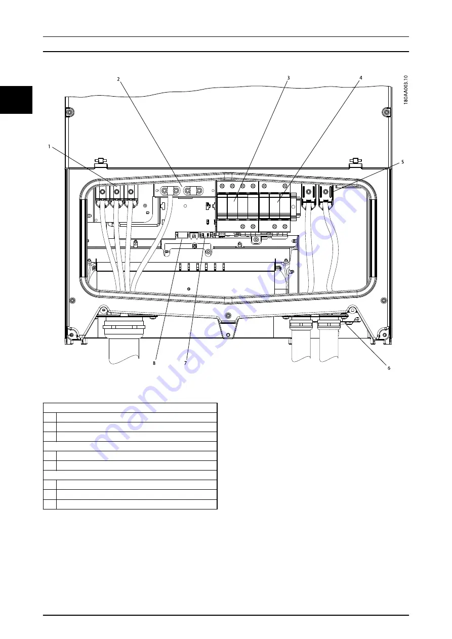
Illustration 2.5 Overview of Installation Area
PELV (Safe to touch)
2
Equipment grounding
7
Ethernet interface x 2
8
RS-485 interface (not in use)
Live Part
1
AC connection terminals
5
PV connection terminals
Other
3
Surge Protection AC
4
Surge Protection DC
6
PV load switch (optional)
2.3.2 Functional Safety
The inverter is designed for international use, with
functional safety circuit design meeting a wide range of
international requirements (see
Single-fault Immunity
The functional safety circuit has a fully redundant built-in
single-fault detection. If a fault occurs, the inverter
disconnects from the grid immediately. The method is
active and covers all circuitry within the residual current
monitoring, both for continuous levels and sudden
changes. All functional safety circuits are tested during
start-up to ensure safe operation. If a circuit fails more
than 1 out of 3 times during the self-test, the inverter
enters fail safe mode. If the measured grid voltages, grid
frequencies, or residual current during normal operation
differ too much between the 2 independent circuits, the
inverter ceases to energise the grid and repeats the self-
test. The functional safety circuits are always activated and
cannot be disabled.
Isolation
During the self-test, the inverter has an isolation measuring
system that detects whether the isolation in the PV system
is above the required level. This is done before the inverter
Inverter Overview
8
L00410648-02_02 / Rev. date: 2014-10-03
2
2


