4 Product Overview
SMA Solar Technology AG
Installation Manual
15
EDMM-WAGO-IO-IA-en-11
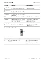
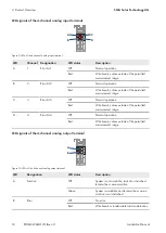
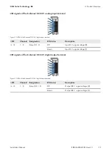
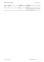
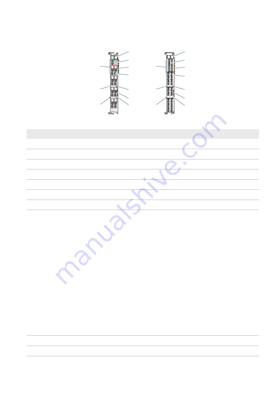
Status LEDs on the I/O modules indicate the operating state and error-free terminal bus communication via red/green
signals.
A
B
C
D
E
F
C
E
A
B
C
D
E
F
C
E
G
G
G
G
Figure 6: I/O module configuration (example)
Position
Designation
A
Labeling option with Mini WSB
B
Status LEDs
C
Data contacts
D
CAGE CLAMP® connections
E
Power co24 V
F
Release tab
G
Power contacts 0 V
For detailed information on evaluation of the LED statuses (see Section 4.8 "LED Signals", page 16).
4.5
Bus end terminal 750-600
The bus end terminal 750-600 is used to terminate the internal terminal bus of a fieldbus node. This bus termination
ensures correct data transmission via terminal bus.
The bus end terminal 750-600 is not equipped with any power contacts, CAGE CLAMP® connections or LED
signaling.
4.6
Hardware address (MAC ID)
The WAGO-I/O-SYSTEM 750 has an internationally unique physical address: the MAC ID (Media Access Control
Identity).
The MAC ID is printed on a paper strip with two self-adhesive tear-off labels on the left side of the field bus coupler/
controller. The MAC ID has a fixed length of 6 bytes (48 bits) in hexadecimal notation. The first 3 bytes provide
information about the manufacturer (e.g. 00:30:DE for WAGO). The other 3 bytes contain the consecutive serial
number of the device hardware.
4.7
Design guidelines and standards
DIN 60204
Electrical equipment of machines
DIN EN 50178
Electronic equipment for use in power installations (replacement for VDE 0160)
EN 60439
Low-voltage switch gear and controlgear assemblies
Summary of Contents for Modbus EDMM-10
Page 54: ...www SMA Solar com...


