6 Connection
SMA Solar Technology AG
Installation Manual
EDMM-WAGO-IO-IA-en-11
28
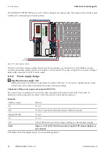
The WAGO-I/O-SYSTEM 750 requires a 24 V direct voltage for the system supply. The voltage is fed in via the supply
module and is protected against reverse polarity.
GND
+24 V DC
+24 V DC (-15 % / +20 %)
0 V
Figure 16: System supply overview
The fed in 24 V direct voltage supplies all internal system components, e.g. the electronics of the fieldbus coupler/
controller, the fieldbus interface and the I/O modules, via the local bus (5 V system voltage). The 5 V system voltage is
galvanically connected to the 24 V system supply.
6.5.4
Power supply design
Regulated power supply units
Stable grid supply cannot always be guaranteed anywhere all the time. For this reason, regulated power supply
units must be used in order to guarantee the quality of the supply voltage.
Calculation of the power supply unit output (at DC 24 V):
The internal current consumption for each I/O module is specified in the technical data of the I/O module. To
determine overall consumption, the values of all of the modules in the node are added up.
Example:
Fieldbus coupler:
280 mA
DI:
37 mA
DO:
10 mA + output load of all channels (max. 500 mA/channel)
TempIN (PT100):
10 mA
AI:
15 mA
AO:
120 mA (80 mA for 4 x 20 mA o effi internal power supply)
Total
Approx. 1.5 A at 24 V (with a maximum load of 120 mA per digital out-
put channel)
With higher loads at the digital outputs, it is correspondingly greater.
Summary of Contents for Modbus EDMM-10
Page 54: ...www SMA Solar com...


