6 Connection
SMA Solar Technology AG
Installation Manual
EDMM-WAGO-IO-IA-en-11
34
AI 1
AI 3
AI 2
AI 4
24 V
0 V
1
5
2
6
3
7
4
8
AO
10 nF
270 pF
A
D
ground
ground
ground
logic
error
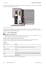
Figure 27: Circuitry of the 4-channel analog input terminal 4 mA to 20 mA
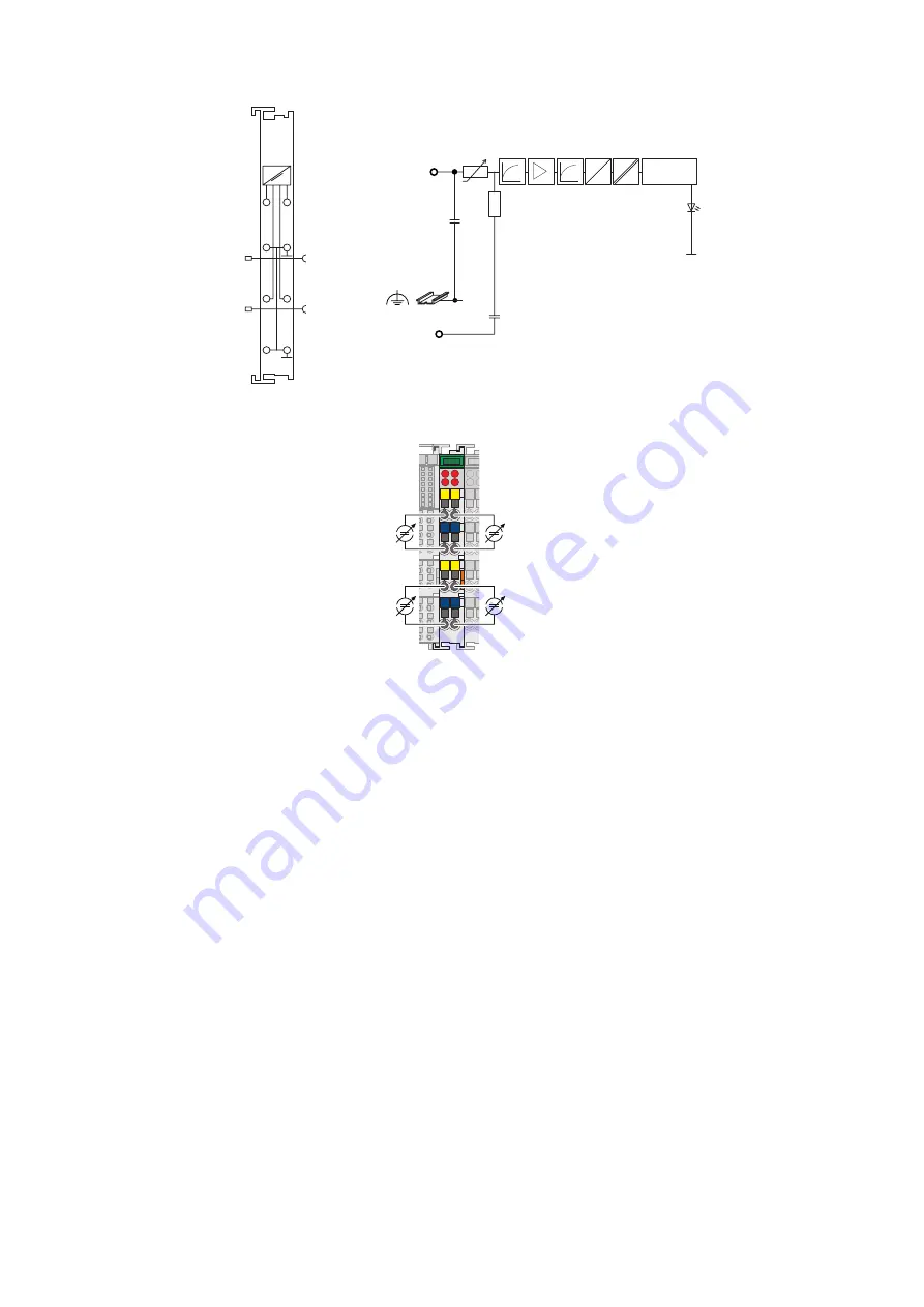
Figure 28: Example connection of the 4-channel analog input terminal 4 mA to 20 mA
6.5.5.5
4-channel analog output terminal 0 mA to 20 mA
The 4-channel analog output terminal 0 mA to 20 mA has four output channels and generates signals that must be
strictly restricted to 4 mA to 20 mA by an internal scaling installed in Data Manager M. This allows for direct wiring of
four 2-conductor actuators on the bus terminal. The actuators are connected to the CAGE CLAMP® connections AO 1
and ground or AO 2, AO 3, AO 4 and ground. The channels have one shared ground potential.
A green LED indicates the operating state and error-free terminal bus communication. A red error LED indicates a short
circuit or an overload.
Summary of Contents for Modbus EDMM-10
Page 54: ...www SMA Solar com...


