6 Connection
SMA Solar Technology AG
Installation Manual
EDMM-WAGO-IO-IA-en-11
36
Figure 31: Example connection of the 4-channel analog output terminal 0 mA to 20 mA
6.5.6
Connection to Data Manager M
NOTICE
Damage to the product due to incorrect connection
• Only use devices with an Ethernet/RJ-45 connection in LANs.
• Never connect these devices with telecommunications networks such as with analog or ISDN telephone
networks.
Two RJ-45 connectors are used to establish the connection to Data Manager M. The RJ-45 connectors are connected
to the fieldbus coupler via an integrated network switch. The integrated network switch words in store-and-forward
mode and supports a data transfer rate of 10/100 Mbit for every port as well as the full duplex, half duplex, and auto
negotiation transfer modes.
The RJ-45 jacks are wired in accordance with the requirements for 100BASE-TX. In accordance with the Ethernet
standard, a Cat 5e twisted-pair cable must be used as the connecting cable. S-UTP (screened unshielded twisted pair)
and STP (shielded twisted pair) cables with a maximum segment length of 100 m can be used. The connection point is
designed so that the system can be installed in an 80 mm-high switch cabinet is possible after the connector is plugged
in.
A B
C D
E F
G H
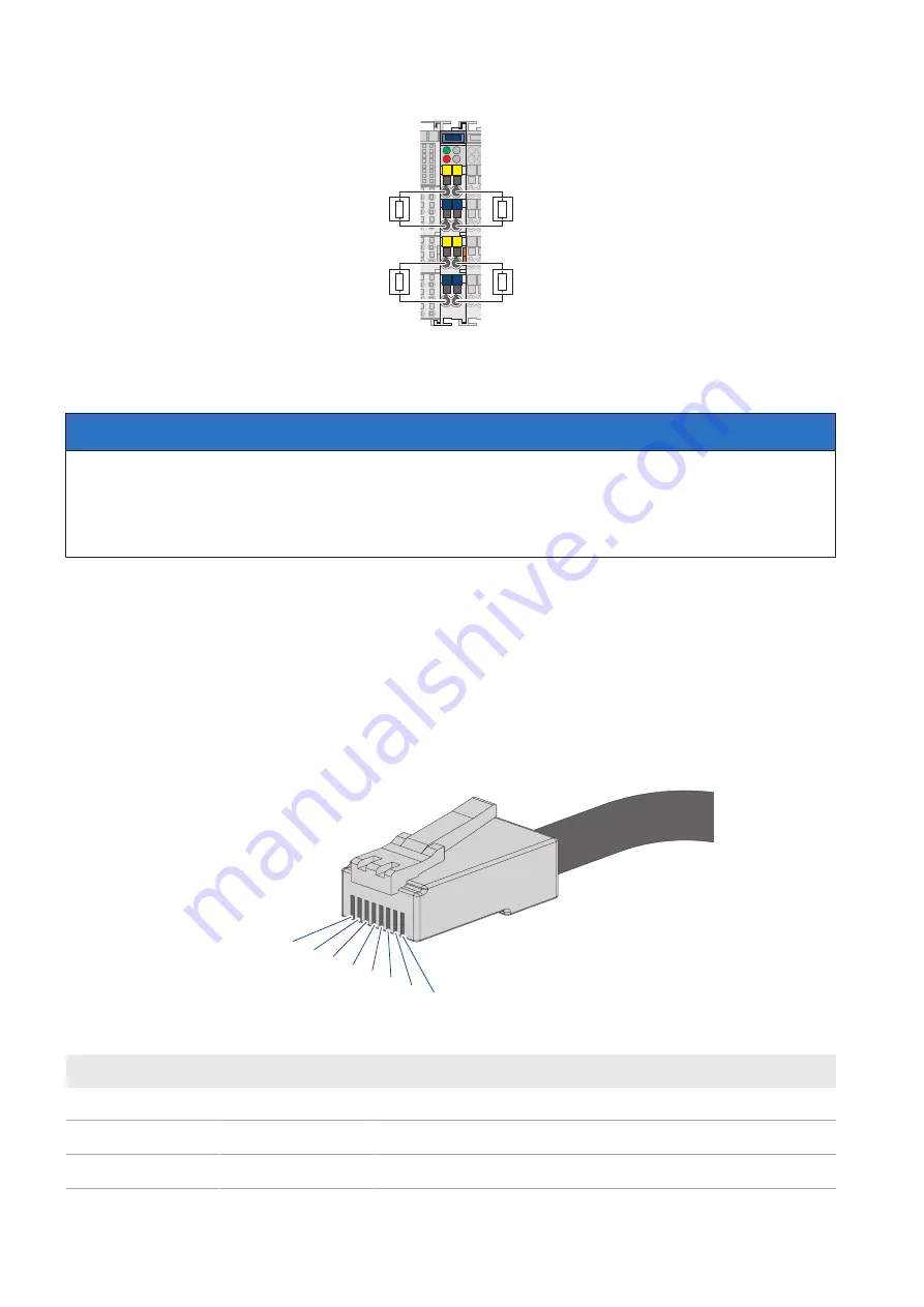
Figure 32: Pin assignment of the fieldbus connection
Position
Signal
Designation
A
TD +
Transmit data +
B
TD -
Transmit data -
C
RD +
Receive data +
Summary of Contents for Modbus EDMM-10
Page 54: ...www SMA Solar com...

