4 Product Overview
SMA Solar Technology AG
Installation Manual
EDMM-WAGO-IO-IA-en-11
14
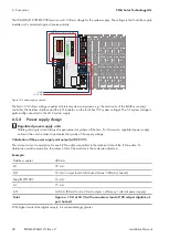
The supply module provides the 24 V supply potential via the power contacts, the 0 V supply potential, and das
ground potential for the field level and for subsequent bus terminals. A green status LED indicates the 24 V operating
voltage at the power contacts.
D
A
B
C
E
F
Figure 5: Supply module connections
Position
Connection
Designation
Designation
A
2
24 V
Feed-in: 24 V field supply
D
6
Feed-in: 24 V field supply
B
3
0 V
Feed-in: 0 V field supply
E
7
Feed-in: 0 V field supply
C
4
Ground
Feed-in: Ground field sup-
ply
F
8
Feed-in: Ground field sup-
ply
For detailed information on evaluation of the LED statuses (see Section 4.8 "LED Signals", page 16).
4.4
I/O modules
Different sensors and actuators are connected to the WAGO-I/O-SYSTEM 750 via the I/O modules. Single-, multiple-,
or fine-wire conductors can be connected via the CAGE CLAMP® connections. The terminal bus is responsible for
communication between the fieldbus coupler/controller and the individual I/O modules. The terminal bus is comprised
of 6 self-cleaning gold-spring contacts. Field supply voltage is used for the voltage supply.
The I/O modules receive the 24 V supply potential and the 0 V potential for the field level via the power contacts of
the respective upstream I/O module or the supply module and also conduct this potential to the downstream I/O
module.
Summary of Contents for Modbus EDMM-10
Page 54: ...www SMA Solar com...


