6 Connection
SMA Solar Technology AG
Installation Manual
25
EDMM-WAGO-IO-IA-en-11
6
Connection
6.1
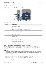
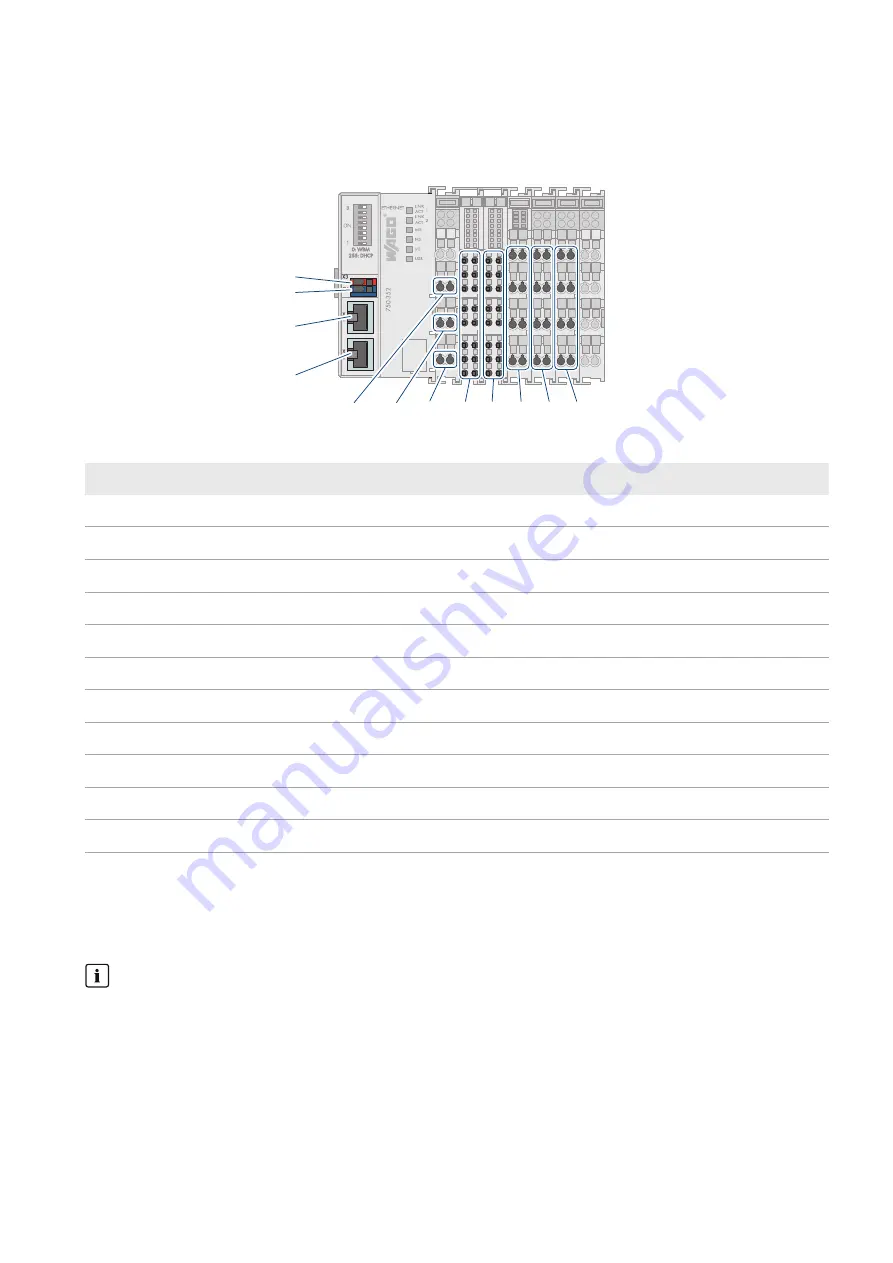
Overview of the Connection Area
D
E
F
G H
I
J
C
C
B
A
K
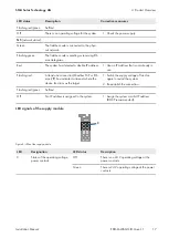
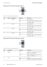
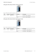
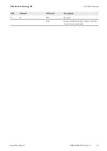
Figure 15: Overview of the connection area
Position
Designation
A
DC 24 V system supply
B
DC 0 V system supply
C
Fieldbus connection 2 x RJ-45 as a 2-port Ethernet switch
D
Feed-in: DC 24 V field supply
E
Feed-in: DC 0 V field supply
F
Feed-in: Ground field supply
G
8x digital input
H
8x digital output
I
2x analog input for PT100 sensors
J
4x analog input 4 mA to 20 mA
K
4x analog output 0 mA to 20 mA
6.2
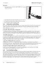
Connecting the conductor the CAGE CLAMP®
The CAGE CLAMP® connection is used to connect the conductor for system supply and supply of the various
components of the I/O modules The CAGE CLAMP® connections are designed for single-, multiple- or fine-wire
conductors.
Only connect one conductor per CAGE CLAMP®
You may only connect one conductor to each CAGE CLAMP® connection. Multiple individual conductors may
not be connected to one connection. If multiple conductors need to be placed on one connection, connect them
using upstream wiring.
Requirements:
☐ Conductor cross-section, single-wire: 0.08 mm² to 2.5 mm² (AWG 28 to AWG 14)
☐ Conductor cross-section, fine-wire: 0.25 mm² to 2.5 mm² (AWG 24 to AWG 14)
☐ Insulation stripping length: 8 mm to 9 mm (0.315 in to 0.354 in)
Summary of Contents for Modbus EDMM-10
Page 54: ...www SMA Solar com...


