6 Connection
SMA Solar Technology AG
Installation Manual
EDMM-WAGO-IO-IA-en-11
26
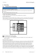
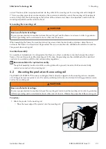
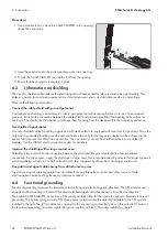
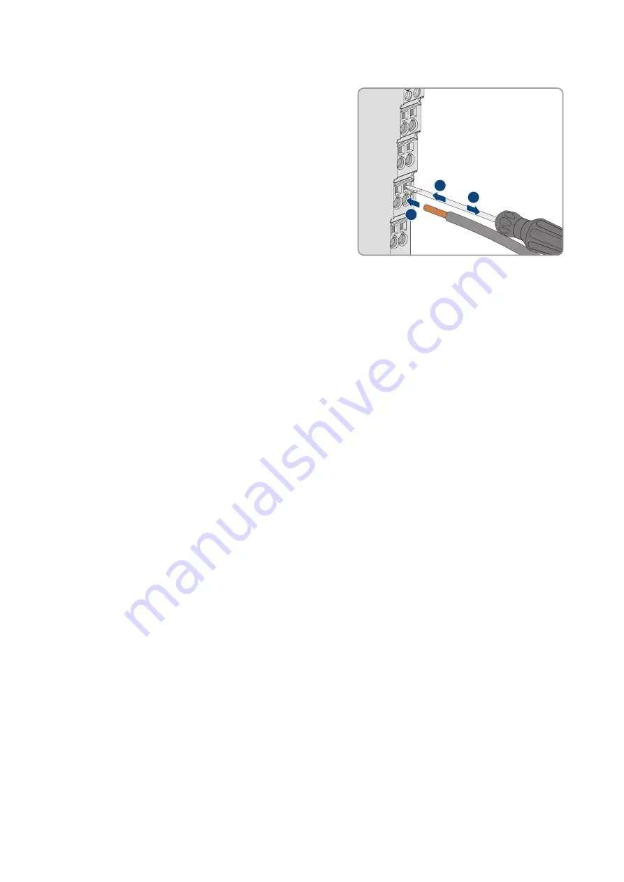
Procedure:
1. Use a suitable tool to unlock the CAGE CLAMP® in the opening
above the connection.
2
1
3
2. Insert the conductor into the corresponding connection opening.
3. To lock the CAGE CLAMP®, remove the tool from the opening.
4. Ensure that the conductor is securely in place.
6.3
Information on shielding
The use of a shielded cable reduces the electromagnetic influences and therefore increases the signal quality. This
makes it possible to avoid measurement errors, data transmission errors, and disturbances due to overvoltage.
Observe the following information:
Connect the cable shield with ground potential
Comprehensive shielding is mandatory in order to guarantee the technical specifications in terms of measurement
precision. Establish the connection between the cable shield and ground potential at the opening of the cabinet or
enclosure. This diverts any disturbances and keeps them far away from the devices within the cabinet or enclosure.
Use shielded signal cables
Use only shielded cables for analog signals and with devices that are equipped with terminals for the shield. This is the
only way to guarantee that the precision and interference immunity for the respective device can be achieved in the
event of disturbances that affect the signal cable. You can directly connect the shielded cable to some of the I/O
modules. Use the WAGO shield connection system for all others.
Improve the shielding with a large contact area
Shielding is improved when the connection between the shield and the ground potential is a low-impedance
connection. For this purpose, apply the shield over a large area. This is recommended in particular for larger systems in
which equalizing currents run or high pulsed currents (e.g. triggered by atmospheric discharge) could occur.
Keep data and signal cables away from disturbance sources
Lay data and signal cables separate from all cables that carry three-phase current and other sources of high
electromagnetic emissions (e.g. frequency inverters or drives).
6.4
Functional grounding
Functional grounding increases the interference immunity against electromagnetic influences. The I/O modules are
equipped with a mounting rail contact that diverts electromagnetic disturbances away from the mounting rail.
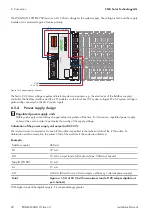
The bottom CAGE CLAMP® connections of the supply modules allow for the option to connect a field.side functional
grounding. The bottom spring contact of the three power contacts makes this potential available to the I/O module
installed to the right. The I/O modules are equipped with a measuring contact that picks up this potential. In terms of
the functional grounding, this forms a potential group together with the I/O module installed on the left.
Summary of Contents for Modbus EDMM-10
Page 54: ...www SMA Solar com...


