background image

Sunny Boy 2500U 


Installation and Operator’s Manual 

SB2500U-11:NE  

3

 - 

SMA Regelsysteme GmbH


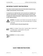
IMPORTANT SAFETY INSTRUCTIONS 

This manual contains important instructions that shall be followed during in-

stallation and maintenance of the Sunny Boy.  

To reduce the risk of electrical shock, and to ensure the safe installation and 

operation of the Sunny Boy, the following safety symbols have been placed 

throughout this technical description to indicate dangerous conditions and im-

portant safety instructions.


WARNING: 

This indicates a fact or feature very important for the safety of

the user and / or which can cause a serious hardware defect if not applied

appropriately. 

Use extreme caution when performing this task. 


NOTE: 

This indicates a feature that is important either for optimal and

comfortable usage or optimal operation of the system. 

Follow instructions closely. 


EXAMPLE: 

This indicates an example. 


SAVE THESE INSTRUCTIONS


Summary of Contents for MyGen 1500

Page 1: ...SB2500U 11 NE3801 Grid Tied String Inverter for Photovoltaic Systems Issue 1 2 Installation and Operator s Manual Sunny Boy SWR 2500U...

Page 2: ...Sunny Boy 2500U Installation and Operator s Manual SB2500U 11 NE 2 SMA Regelsysteme GmbH...

Page 3: ...ng safety symbols have been placed throughout this technical description to indicate dangerous conditions and im portant safety instructions WARNING This indicates a fact or feature very important for...

Page 4: ...tions and cautionary markings in the technical description and on the Sunny Boy and the PV array Connecting the Sunny Boy to the electrical utility grid must only be done after receiving prior approva...

Page 5: ...3 2 Connection to Electrical Utility Grid 16 3 Commissioning 20 4 Operation and Failure Indication LEDs 24 4 1 Operation Indicator 27 4 2 Ground Fault Indicator 30 4 3 Failure Indication 31 4 4 Openi...

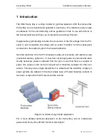
Page 6: ...ection to the electricity grid in the house distribution Here the electricity from the PV modules provides all consumers with electric power household devices lights etc In case that not enough power...

Page 7: ...amages The Sunny Boy inverters are thoroughly checked before they are shipped Even though they are delivered in a sturdy packaging which can be recycled the inverters can be damaged which is the forwa...

Page 8: ...while the PV plant is designed In the following you will find a summary of the most important criteria Criteria for device mounting Due to the high protection class NEMA 4X of the enclosure the instal...

Page 9: ...e NEC Section 690 64 b 2 Do not expose the string inverter to direct sunlight if necessary in stall a shading roof A minimum distance of 8 inch 200 mm must be clear above the in verter for ventilation...

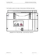
Page 10: ...e Sunny Boy 434 50 mm Drilling Template for the Sunny Boy 2000 2500 3000 63 50 mm position of the holes on the top for 6 mm screws bottom hole 6 mm diam distance between the holes on the top 217 50 mm...

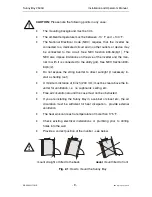
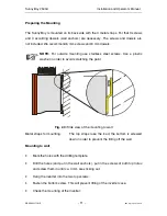
Page 11: ...screws Use a plastic washer in order to avoid scratching the paint Fig 2 3 Side view of the mounting to wall Metal straps for mounting The top straps take the load the bottom is screwed down in order...

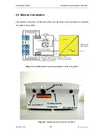
Page 12: ...3 Electric Connection The electric connection of the Sunny Boy can be done once the device is correctly mounted in its position Fig 2 4 Simplified electrical wiring diagram of the PV system Fig 2 5 Un...

Page 13: ...sizes up to 10 AWG 5 26 mm 2 are ac cepted by the AC and DC terminals on the printed circuit board WARNING The connection of the Sunny Boy to the DC voltage from the PV string and the AC voltage of th...

Page 14: ...of the Sunny Boy 2500U You now have the opened Sunny Boy in front of you see Fig 2 7 and can see the position of components and clamps relevant for you You will find The internal grid fuse WARNING A...

Page 15: ...Sunny Boy 2500U Installation and Operator s Manual SB2500U 11 NE 15 SMA Regelsysteme GmbH Fig 2 7 Interior of the Sunny Boy 2500U DC Connection Place for Piggy Back Resistors Grid Fuse AC Connection...

Page 16: ...n point should be as low as possible to avoid an increase of the AC voltage to non permissible values while the Sunny Boy feeds to the grid This also results in a higher system efficiency EXAMPLE The...

Page 17: ...ting on the inside of the Sunny Boy with the nut Pull the wires through the conduit into the interior of the Sunny Boy Connect the wire L1 to the terminal labeled L in the Sunny Boy see Fig 2 8 Connec...

Page 18: ...type of PV module used it is possible to connect one single string or several parallel strings Therefore there are three connections for both the and the pole Within the device these connections are c...

Page 19: ...nut Do the same at the DC dis connect enclosure Ensure all circuit breakers in the DC disconnect enclosure are in the OFF position Route the wires from the DC disconnect enclosure through the conduit...

Page 20: ...bottom are closed with the seals When putting the lid on make sure the seal in the inner side of the lid is placed correctly When screwing the inner screws make sure that the thread in the Sunny Boy...

Page 21: ...isconnect enclosure Now the Sunny Boy is supplied with the DC voltage and starts to operate If the PV panel is isolated from earth first the yellow and red LEDs and after approx 20 seconds only the re...

Page 22: ...laced You will find a description of the correct type in chapter 4 2 Fig 3 1 Diagram of commissioning Switch DC ON and wait 20 seconds Green LED blinking Remove GFDI Fuse Insert GFDI Fuse Only Red LED...

Page 23: ...internal consumption which it takes from the PV panel If you measure the voltage of the PV modules you must keep in mind the inverter s internal consumption that will have an effect on your measureme...

Page 24: ...he user does not notice The user can obtain the inverter s operating status from the 3 integrated LEDs on the lid see Table 4 1 Operation indication overview The green LED Operation describes the curr...

Page 25: ...rth Fault St rung Failure Photovoltaik Stringwechselrichter Photovoltaic string inverter SWR 2500 Fig 4 1 Front view of Sunny Boy 2500U Description of the symbols used in the following section LED off...

Page 26: ...ions are being checked green red yellow feeding grid MPP or constant voltage mode normal operation green red yellow derating mode Reduction of power fed to the grid due to in creased temperature of th...

Page 27: ...e on The Sunny Boy control system is initializing The string voltage to the inverter is between approx 120 V and 240 V The supply is suf ficient for the system control and not quite sufficient for fee...

Page 28: ...by the user with the Sunny Boy Control or the program Sunny Data The Sunny Boy remains in this condition until set to MPP Operation or Constant Voltage Operation Waiting Grid Monitoring Green LED bli...

Page 29: ...he PV modules to the voltage with the maximum output power Constant Voltage operation The voltage from the PV modules can be set to a fixed value This value is transmit ted to the Sunny Boy with the S...

Page 30: ...se have a look at chapter 3 First switching on If the ground fault of the PV panel is removed the inverter switches from permanent de vice disable to GFDI Fuse open failure and the yellow LED is off T...

Page 31: ...The yellow failure LED is permanently on This is a failure of the utility monitoring or the automatic disconnection device MSD The Sunny Boy has detected a failure in the disconnection device and has...

Page 32: ...ailure which has one of the following reasons Low grid voltage VAC min see table 9 2 High grid voltage VAC max see table 9 2 Low grid frequency fAC min see table 9 2 High grid frequency fAC max see ta...

Page 33: ...imes The code is sent three times If the failure persists the indication begins once again The Sunny Boy has detected a failure based on the utility impedance values The criteria for the grid impedanc...

Page 34: ...D is activated for 5 seconds is out for 3 seconds and then blinks four times The code is sent three times If the failure persists the indication is repeated The input voltage is too high The PV panels...

Page 35: ...t Failure The yellow failure indication LED is activated for 5 seconds is out for 3 seconds and then blinks five times The code is sent three times If the failure persists the indication is repeated T...

Page 36: ...ons are for use by qualified personnel only To reduce the risk of electric shock do not perform any sevicing other than specified in this technical description unless you are qualified to do so When w...

Page 37: ...Fig 2 7 and can see the posi tion of components and clamps relevant for you You will find The internal grid fuse WARNING For continued protection against risk of fire replace only with same types and...

Page 38: ...n conditions the enclosure type NEMA 4X cannot be guaranteed any more When mounting the Sunny Boy outside moisture can get into the device and damage the electronics WARNING Make sure that the lid of...

Page 39: ...e considerable harm to people Only a qualified elec trician may work on the device especially open it While upgrading the Sunny Boy interface the operator can get into touch both with elec tronic comp...

Page 40: ...desired piggy back module onto the required slot When plugging on the piggy back please make sure no socket of the piggy back plug in contacts remains open Connect the cables for RS232 or RS485 No ca...

Page 41: ...ut voltage of the Vpv control Iac current to the grid Vac grid voltage Fac grid frequency Pac power fed to grid Zac grid impedance Vpv _PE PV voltage to earth Ipv current from PV panels E Total energy...

Page 42: ...tage F MSD FAC different values between BFR and SRR for grid frequency F MSD Meas different values between BFR and SRR for dI Fac Vac or Zac F K1 Close Relay test failed F K1 Open Relay test failed F...

Page 43: ...accuracy resulting from these dif ferent temperatures Unit Range Resolution Maximal fail ure Display Measurement U 77 F input voltage UPV V 0 650 V 1 V 1 12 V 2 input current IPV mA 0 12000 mA 1 mA 12...

Page 44: ...conduct the following steps in case your PV plant does not operate correctly check the connection to the grid and to the PV panels pay attention to all safety measures listed in chapter 2 Installation...

Page 45: ...ntrol or a PC with Sunny Data is present What failure is indi cated Can you reproduce the failure How can you reproduce it Has this failure always occurred What were the ambient conditions as the fail...

Page 46: ...nal warranty period for the delivered item Evidence SMA will only render warranty services if the rejected device is sent back to SMA together with a copy of the account the distributor has issued for...

Page 47: ...e g industrial power supply grids or in the neighborhood of irregular consumers unshielded motors switching power supplies converters etc Further more the simultaneous operation of babyphones may lead...

Page 48: ...at its lowest point Therefore it has to take into account the lowest possible ambient temperature of the PV panel when planning the PV plant Based on this temperature and knowing the type of PV modul...

Page 49: ...the PV panel Therefore the Sunny Boy has a flexible MPP voltage range There is a fixed ratio between the minimum MPP voltage VMPP min the Sunny Boy loads onto the PV panel and the grid voltage VAC as...

Page 50: ...234 V 550 V DC Max open circuit voltage under all conditions VPVOC 600 V DC Max input current IPV 13 A DC Max DC power PPV 2710 W DC Recommended PV panel power up to 3000 WP Voltage ripple VPP 10 All...

Page 51: ...AC 0 5 P ACnom Phase shift ref fundamental 0 Utility monitoring Islanding protection V AC f AC in accordance with UL 1741 Ground Fault Protection IDIF in accordance with UL1741 All pole disconnection...

Page 52: ...ity 0 100 class 3K6 Size Weight Enclosure type NEMA 4X Size w x h x d 17 08 x 11 61 x 8 42inch 434 x 295 x 214 mm Weight 70 lb 32 kg Certifications EMI in compliance with FCC regulations DIN EN 50081...

Page 53: ...SMA Regelsysteme GmbH 12 0 2 0 4 0 6 0 8 0 10 0 250 300 350 400 450 500 550 600 I A PV U A P V Fig 7 2 Maximal Input Current of the Sunny Boy 2500U 3000 500 1000 1500 2000 2500 250 300 350 400 450 500...

Page 54: ...n and Operator s Manual SB2500U 11 NE 54 SMA Regelsysteme GmbH 0 0 1 0 2 0 3 0 4 0 5 0 6 0 7 0 8 0 9 1 0 00 0 25 0 50 0 75 1 00 1 25 1 50 1 75 2 00 2 25 2 50 PAC kW efficiency P AC P DC Fig 7 4 Effici...

Page 55: ...6 V Const Setval V 250 600 600 Installer Plimit W 2500 Fixed 23 Testcurrent Zac MA 0 15000 8000 Installer 28 Vac Min V 180 300 213 Installer 29 Vac Max V 180 300 262 Installer 30 Fac delta Hz 0 4 5 0...

Page 56: ...Sunny Boy 2500U Installation and Operator s Manual SB2500U 11 NE 56 SMA Regelsysteme GmbH 8 Appendix Certificate for Sunny Boy 2500U Underwriters Laboratories Listing Document dated 8 May 2001...

Page 57: ...Sunny Boy 2500U Installation and Operator s Manual SB2500U 11 NE 57 SMA Regelsysteme GmbH...

Page 58: ...ta User Manual Sunny Data Control User Manual Sunny Boy Control User Manual SWR COM Socket Powerline Modem Sunny Boy Info periodical newsletter with up to date information SMA CD products technical do...

Page 59: ...aily and offers the newest information concerning the Sunny Boy inverter family the newest software help concerning problems with your PV plant and of course all you might want to know about SMA Regel...

Page 60: ...95 Telefax 530 274 7271 eMail info sma america com Internet http www sma america com SMA in Europe Address SMA Regelsysteme GmbH Hannoversche Stra e 1 5 D 34266 Niestetal Telephone 0049 561 9522 0 ope...

Reviews: