background image

6  Electrical Connection

SMA Solar Technology AG

Operating manual

19

NA-BOX-12-3-20-BE-en-12

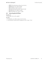
6.1.2

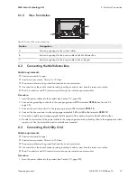
View from Below

B

C

A

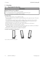
Figure 8: Position of the enclosure openings

Position

Designation

A

Enclosure openings for the control cables

B

Enclosure openings for the power cables of the Multicluster-Box

C

Enclosure openings for the power cables of the utility grid

6.2

Connecting the Multicluster-Box

Cable requirements:

☐ Conductor material: copper

☐ Conductor cross-section: 50 mm² to 150 mm²

☐ The power cables must be ground-fault and short-circuit protected.

☐ Line conductors, the neutral conductor and grounding conductor must have the same cross-section.

☐ The AC conductors and DC conductors must always be routed in separate cables.

Procedure:

1. Insert the power cables into the product (see Section 9.2, page 25).

2. Connect the grounding conductor to the spring-cage terminal 

PE

 at terminal 

X201:6

 (see Section 9.3,

page 26).

3. Connect the neutral conductor to the spring-cage terminal 

N

 at terminal 

X201:10

.

4. Connect the line conductors to the spring-cage terminals 

L1

L2

 and 

L3

 at the terminals 

X201:7-9

.

5. Ensure that a right-hand rotating magnetic field is present at the connection point of the Multicluster-Box.

6. Provide for strain relief of the power cables in the spring-cage terminal by attaching them to the appropriate cable

support rail. Use the strain reliefs and counter-sleeves provided.

6.3

Connecting the Utility Grid

Cable requirements:

☐ Conductor material: copper

☐ Conductor cross-section: 50 mm² to 150 mm²

☐ The power cables must be ground-fault and short-circuit protected.

☐ Line conductors, the neutral conductor and grounding conductor must have the same cross-section.

☐ The AC conductors and DC conductors must always be routed in separate cables.

Procedure:

1. Insert the power cables into the product (see Section 9.2, page 25).
Summary of Contents for NA-BOX 12

Page 1: ...SUNNY ISLAND NA BOX 12 3 20 BE en 12 Version 1 2 ENGLISH Operating manual NA BOX 12...

Page 2: ...lusion of implied warranties may not apply in all cases under some statutes and thus the above exclusion may not apply Specifications are subject to change without notice Every attempt has been made t...

Page 3: ...16 6 Electrical Connection 18 6 1 Overview of the Connection Area 18 6 1 1 Interior View 18 6 1 2 View from Below 19 6 2 Connecting the Multicluster Box 19 6 3 Connecting the Utility Grid 19 6 4 Conn...

Page 4: ...Table of Contents SMA Solar Technology AG Operating manual NA BOX 12 3 20 BE en 12 4 12 Technical Data 35 13 Contact 38...

Page 5: ...and directives Knowledge of and compliance with this document and all safety information 1 3 Levels of warning messages The following levels of warning messages may occur when handling the product DA...

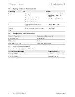
Page 6: ...Minutes Connects several elements to be selected Select Settings Date Button Key Button or key to be selected or pressed Select Enter 1 6 Designation in the document Complete designation Designation...

Page 7: ...he product e g changes or modifications are only permitted with the express written permission of SMA Solar Technology AG Unauthorized alterations will void guarantee and warranty claims and in most c...

Page 8: ...s due to hot components Some components and terminals inside the product can become hot during operation Touching hot components or terminals can result in burn injuries Wear suitable personal protect...

Page 9: ...product must only be closed during operation Store the product in a dry and covered location when closed Observe storage conditions Effects of an emergency disconnection Emergency disconnection on the...

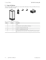
Page 10: ...distributor if the scope of delivery is incomplete or damaged B D C E A Figure 1 Components included in the scope of delivery Position Quantity Designation A 1 NA Box B 10 Strain relief with counter...

Page 11: ...product You will find the following information on the type label Device type Model Serial number Serial No or S N Date of manufacture Device specific characteristics C Fuse holder 6 A Used as recept...

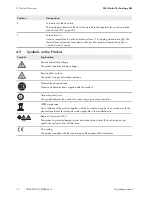
Page 12: ...electrical voltage The product operates at high voltages Beware of hot surface The product can get hot during operation Observe the documentation Observe all documentation supplied with the product G...

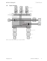
Page 13: ...ucture BATFUSE SUNNY ISLAND NA BOX Load contactor MULTICLUSTER BOX Main AC distribution board PV main distribution box not included in the delivery BATTERY Generator contactor GENERATOR LOAD PV MODULE...

Page 14: ...35 The mounting location should be freely and safely accessible at all times without the need for any auxiliary equipment such as scaffolding or lifting platforms Non fulfillment of these criteria ma...

Page 15: ...paring the Mounting Location WARNING Danger to life due to fire or explosion if mounted at an unsuitable location Mounting the product in areas with a high fire hazard can result in fire This can resu...

Page 16: ...ICE Damage to the product due to sand dust and moisture ingress after setting down on unsuitable surface Setting the product down on an unsecured or uneven surface may cause the product to warp and al...

Page 17: ...BE en 12 6 CAUTION Risk of injury if the Multicluster Box tips over The Multicluster Box is heavy and may tip over if not properly fastened to the support surface This can result in crushing injuries...

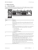
Page 18: ...nals L1 L2 and L3 to connect the line con ductors of the Multicluster Box D Terminal X201 6 with spring cage terminals PE to connect the grounding conductor of the Multicluster Box E Terminal X201 10...

Page 19: ...the grounding conductor to the spring cage terminal PE at terminal X201 6 see Section 9 3 page 26 3 Connect the neutral conductor to the spring cage terminal N at terminal X201 10 4 Connect the line c...

Page 20: ...cage terminals with the control cables 1 2 5 4 6 3 3 4 7 6 5 1 2 8 9 10 11 12 13 PE X210 X210 PE PE PE PE A B C D E F Figure 9 Overview of the spring cage terminals Position Designation A Multicluste...

Page 21: ...ox voltage measurement X211 6 7 Multicluster Box generator contactor interlock X211 8 9 NA Box AC contactor 2 interlock X211 11 12 NA Box AC contactor 1 interlock 6 5 Mounting the Kick Plates Requirem...

Page 22: ...V system protection documentation Only operate the NA Box when the grid and PV system protection device is secured against unauthorized access Requirements The NA Box must be correctly mounted see Sec...

Page 23: ...r let the product cool down 1 Switch off all loads 2 Stop the multicluster system on the master of the main cluster see operating manual of the Sunny Island 3 Switch off all Sunny Island inverters see...

Page 24: ...make sure it cannot be reconnected before working on the device Only disassemble the protective covers if the product is disconnected from all voltage sources Wear suitable personal protective equipme...

Page 25: ...pierce as many holes in the membranes of the cable feed through plate as you need for the cables The hole in the membrane must be smaller than the diameter of the cable to be led through Only insert o...

Page 26: ...que 9 Nm 9 3 Connecting Power Cables to Spring Cage Terminals 1 Insert the screwdriver into the clamping contact of the spring cage terminal 2 In the clamping contact press the screwdriver upwards in...

Page 27: ...nsulation is trapped 9 4 Connecting Control Cables to Spring Cage Terminals 1 Insert the screwdriver into the clamping contact of the spring cage terminal 2 Insert the stripped insulated conductor int...

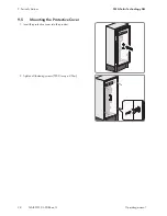
Page 28: ...ic Actions SMA Solar Technology AG Operating manual NA BOX 12 3 20 BE en 12 28 9 5 Mounting the Protective Cover 1 Insert the protective cover into the product 2 Tighten all fastening screws TX30 torq...

Page 29: ...must always be complied with Point out to the end user that if a defect is detected a qualified person is required to perform the next steps Supply of loads temporarily disconnected during testing Du...

Page 30: ...ver if the residual current device does not trip the NA Box and the multicluster system must be disconnected from voltage sources by a qualified person Instruct the end user on the necessary procedure...

Page 31: ...econds The NA Box tie switch Q202 opens The Sunny Island inverter detects a stand alone grid within five seconds and switches to the operating state stand alone grid and opens the NA Box tie switch Q2...

Page 32: ...is recommended Above all the intervals between cleaning work and corrosion protection should be reduced SMA recommends a monthly optical inspection to determine the maintenance requirement Required m...

Page 33: ...13 page 38 10 Check whether the product is free of corrosion damage 11 If the product displays minor corrosion damage treat the affected area as follows Sand the area Clean the area with degreaser Pa...

Page 34: ...fastening screws for later use 3 Disassemble the protective covers and base plates 4 Remove all cables from the product 5 Release and remove the fastening screws on the bottom of the product 6 Mount t...

Page 35: ...up fuse 25 kA Forward current of the back up fuse 17 kA Multicluster Box connection Number of terminals 1 x three phase Rated grid input power 138 kW Rated operating voltage between L and N 230 V Rate...

Page 36: ...45 Hz to 52 Hz Rated impulse withstand voltage 4 kV 2000 m Width x height x depth with base 600 mm x 1400 mm x 435 mm incl 200 mm base Weight 109 kg Maximum operating altitude above mean sea level 200...

Page 37: ...ctive Article 5 Annex I 1 b EMC environment interference immunity as per IEC 61439 1 2011 Interference immunity environment A EMC Directive Article 5 Annex I 1 b EC Declaration of Conformity Yes Opera...

Page 38: ...d batteries Deutschland sterreich Schweiz SMA Solar Technology AG Niestetal Sunny Boy Sunny Mini Central Sunny Tripower 49 561 9522 1499 Monitoring Systems Kommunikationsprodukte 49 561 9522 2499 Hybr...

Page 39: ...w SMA Service com Australia SMA Australia Pty Ltd Sydney Toll free for Australia 1800 SMA AUS 1800 762 287 International 61 2 9491 4200 United Arab Emirates SMA Middle East LLC Abu Dhabi 971 2234 6177...

Page 40: ...www SMA Solar com...

Reviews: