Sunny Mini Central – Installation of the Powerline Kit
Brief Instruction
www.SMA.de
Page 5 of 5
SMA Technologie AG
Hannoversche Str. 1-5
34266 Niestetal
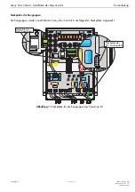
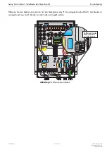
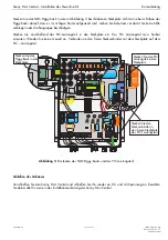
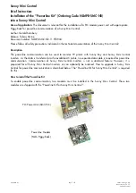
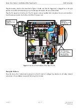
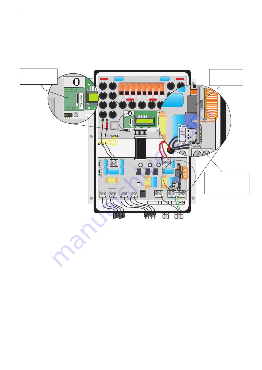
Plug the modules into the slots described in figure 3. Make sure that the Piggy-Back is plugged on in the right
position. Be careful not to bend any pins or to damage the module. Do not use brute force.
Plug the PLC power unit into the slot. The PLC power unit must audibly lock into place. Do not use brute force.
Insert the plug connector into the free slot of the PLC power unit.
MC
MC
MC
MC
2 3 5 7
SMC60-AST
VN30.15/00858
Potter
&Brumfield
Potter
&Brumfield
Potter
&Brumfield
C
B
A
+ +
+ +
- -
- -
0 V
240 V
MC
MC
MC
MC
N
L
PE
N
L1
230 Vac:
A
S2
A
B
B
S1
E-Total 124.4kWh
h-Total 512h
A
S2
A
B
B
S1
Plug the
PLC power unit
into the slot
Insert the plug
connector into the
free slot of the
PLC power unit.
Plug the
Piggy-Back into
the slot.
Figure 3:
Insertion of the Modules of the Powerline Kit
Closing the Enclosure
Close the Sunny Mini Central and reconnect it to the DC and AC voltage. Pay attention to all safety relevant
instructions in the installation manual of the Sunny Mini Central.

