4 Disconnecting the Inverter from Voltage Sources
SMA Solar Technology AG
Replacement Manual
STP50-40-BFS-RM-xx-10
12
4
Disconnecting the Inverter from Voltage Sources
Prior to performing any work on the inverter, always disconnect it from all voltage sources as
described in this section. Always adhere to the prescribed sequence.
WARNING
Danger to life due to electric shock from destruction of the measuring device
due to overvoltage
Overvoltage can damage a measuring device and result in voltage being present in the
enclosure of the measuring device. Touching the live enclosure of the measuring device results in
death or lethal injuries due to electric shock.
• Only use measuring devices with a DC input voltage range of 1000 V or higher.
Firmware update prior to disconnecting the inverter
To ensure trouble-free commissioning of the assembly, update the inverter firmware prior to
disconnecting the inverter.
• Prior to disconnecting the device from all voltage sources, check whether the firmware of
the inverter is up-to-date.
• If necessary, update the firmware.
Procedure:
1. Disconnect the AC circuit breaker and secure it against reconnection.
2. For STP 50-US-40 / STP 33-US-41 / STP 50-US-41 / STP 62-US-41: Set the AC load-break
switch of the inverter to position
O
.
3. Set the DC load-break switch of the inverter to position
O
.
4. If the multifunction relay is used, switch off any supply voltage to the load.
5. Wait until the LEDs have gone out.
6. Use a current clamp to ensure that no current is present in the DC cables.
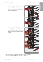
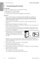
7. Note the position of the DC connector.
8.
DANGER
Danger to life due to electric shock when touching exposed DC
conductors or DC plug contacts if the DC connectors are damaged or
loose
The DC connectors can break or become damaged, become free of the DC cables, or no
longer be connected correctly if the DC connectors are released and disconnected
incorrectly. This can result in the DC conductors or DC plug contacts being exposed.
Touching live DC conductors or DC plug connectors will result in death or serious injury due
to electric shock.
• Wear insulated gloves and use insulated tools when working on the DC connectors.
• Ensure that the DC connectors are in perfect condition and that none of the DC
conductors or DC plug contacts are exposed.
• Carefully release and remove the DC connectors as described in the following.
ENGLISH
Summary of Contents for NR PL-BFS5-JP-01
Page 69: ...1 SMA Solar Technology AG STP50 40 BFS RM xx 10 69 1 5...
Page 72: ...2 SMA Solar Technology AG STP50 40 BFS RM xx 10 72 2 2 5 DC DC DC DC...
Page 73: ...2 SMA Solar Technology AG STP50 40 BFS RM xx 10 73 5 C DC DC AC...
Page 74: ...2 SMA Solar Technology AG STP50 40 BFS RM xx 10 74 DC 1000 V DC 5 C...
Page 75: ...2 SMA Solar Technology AG STP50 40 BFS RM xx 10 75 v v SMA SMA SMA Solar Technology AG...
Page 81: ...5 BFS SMA Solar Technology AG STP50 40 BFS RM xx 10 81 DC DC DC 1 1 DC DC DC PE PE 5 6 X1...
Page 85: ...7 SMA Solar Technology AG STP50 40 BFS RM xx 10 85 12 DC I 13 LED LED 14 15 15 LED 16 5 SMA 17...
Page 86: ...8 SMA Solar Technology AG STP50 40 BFS RM xx 10 86 8 1 SMA Solar Technology AG 2...
Page 245: ...1 SMA Solar Technology AG STP50 40 BFS RM xx 10 245 1 5 1 6 X703 1 X703 6 10...
Page 246: ...1 SMA Solar Technology AG STP50 40 BFS RM xx 10 246 WCtlHz Hz 1 7 BFS OCS OCS...
Page 248: ...2 SMA Solar Technology AG STP50 40 BFS RM xx 10 248 5 DC DC DC DC DC...
Page 249: ...2 SMA Solar Technology AG STP50 40 BFS RM xx 10 249 5 AC DC DC AC...
Page 250: ...2 SMA Solar Technology AG STP50 40 BFS RM xx 10 250 DC 1000 V DC 5 C...
Page 251: ...2 SMA Solar Technology AG STP50 40 BFS RM xx 10 251 SMA SMA SMA Solar Technology AG...
Page 257: ...5 BFS SMA Solar Technology AG STP50 40 BFS RM xx 10 257 DC DC DC 1 1 DC DC DC 1 5 6 X1...
Page 262: ...8 SMA Solar Technology AG STP50 40 BFS RM xx 10 262 8 1 SMA Solar Technology AG 2...
Page 265: ......
Page 266: ...www SMA Solar com...

