5 Disconnecting the Inverter from Voltage Sources
SMA Solar Technology AG
Replacement Manual
CON-SMC46-60A-70HV-RM-xx-10
13
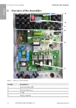
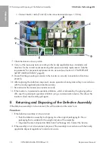
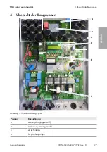
Position
Designation
E
Operation control system assembly (OCS)
F
AC/DC terminal assembly
5
Disconnecting the Inverter from Voltage Sources
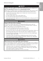
DANGER
Danger to life due to electric shock when live components or DC cables are
touched
When exposed to light, the PV modules generate high DC voltage which is present in the DC
cables. Touching live DC cables results in death or lethal injuries due to electric shock.
• Do not touch non-insulated parts or cables.
• Disconnect the inverter from voltage sources and make sure it cannot be reconnected
before working on the device.
• Do not disconnect the DC connectors under load.
• Wear suitable personal protective equipment for all work on the product.
WARNING
Danger to life due to electric shock from destruction of the measuring device
due to overvoltage
Overvoltage can damage a measuring device and result in voltage being present in the
enclosure of the measuring device. Touching the live enclosure of the measuring device results in
death or lethal injuries due to electric shock.
• Only use measuring devices with a DC input voltage range of 800 V or higher.
Prior to performing any work on the inverter, always disconnect it from all voltage sources as
described in this section.
1. Disconnect the circuit breaker and secure it against reconnection.
2. If an ESS is installed, remove the ESS.
3. If no ESS is installed, disconnect the PV array from the inverter via an external DC load-break
switch (e.g. via a PV combiner box including a load-break switch).
4. Use a current clamp to ensure that no current is present in the DC cables.
5. Ensure that the DC connectors are in perfect condition and that none of the DC conductors or
DC plug contacts are exposed.
6. Carefully loosen the DC connectors.
7. Ensure that no voltage is present at the DC inputs of the inverter.
8. Wait ten minutes before opening the enclosure lid.
9. Loosen all screws of the enclosure lid and remove the enclosure lid.
10. Ensure that no voltage is present between L and N at the AC terminal using a suitable
measuring device.
ENGLISH
Summary of Contents for NR-SMC-CON
Page 51: ...1 SMA Solar Technology AG CON SMC46 60A 70HV RM xx 10 51 1 4 1 5...
Page 54: ...2 SMA Solar Technology AG CON SMC46 60A 70HV RM xx 10 54 DC DC DC DC 5...
Page 56: ...2 SMA Solar Technology AG CON SMC46 60A 70HV RM xx 10 56 5 C v v SMA SMA...
Page 58: ...4 SMA Solar Technology AG CON SMC46 60A 70HV RM xx 10 58 4 F A E B D C 1 A AST B C D...
Page 64: ...8 SMA Solar Technology AG CON SMC46 60A 70HV RM xx 10 64 SMA Solar Technology AG 2...
Page 176: ...www SMA Solar com...

