SMA Solar Technology AG
8 Commissioning
User Manual
REDUCERBOX-BA-en-16
31
8 Commissioning
8.1 Integrating the Power Reducer Box into the Local Network
8.1.1 Procedure
8.1.2 Connecting the Power Reducer Box to the Computer
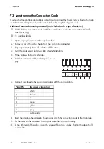
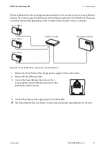
1. Connect the Power Reducer Box to the computer
with the blue Ethernet cable (Ethernet crossover
cable).
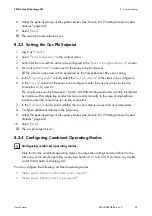
The terminal on the computer is usually identified
with the same symbol as the network terminal on
the Power Reducer Box. If necessary, refer to the
computer manual.
2. Connect the DC plug of the plug-in power supply to the Power Reducer Box.
3. Connect the plug-in power supply plug to the socket-outlet.
☑ The Power Reducer Box is switched on and is operational after approximately 90 seconds.
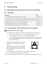
Procedure
See
1 Connecting the Power Reducer Box to the Computer
Section 8.1.2
2 Setting the computer to the Standard Network Settings of the Power Reducer Box Section 8.1.3
3 When using a proxy server: Setting up a Proxy Exception Rule in Internet Explorer Section 8.1.4
4 Setting the Power Reducer Box to Local Network Settings
Section 8.1.5
5 Resetting the Computer to Previous Network Settings
Section 8.1.6
6 Connecting the Power Reducer Box to the Local Network
Section 8.1.7
Recommendation for network cabling
If the supplied patch cable is too short, observe the following patch cable requirements:
• You will need a shielded Ethernet crossover cable of cable type Cat5 or higher.
• For a total length of up to 50 m you can use a cable with AWG26/7.
• For a total length of no more than 100 m, observe the directives for structured cabling in
accordance with EIA/TIA-568, ISO/IEC 11801 and/or EN 50173 (cable for fixed
layout at least AWG24).


