SMA Solar Technology AG
8 Commissioning
User Manual
REDUCERBOX-BA-en-16
43
8. Adopt the general settings of the system statuses (see Section 8.3.5 "Setting General System
9. Select [
Save
].
☑ The reactive power setpoint is set.
8.3.3 Setting the Cos Phi Setpoint
1. Log in as "
Installer
".
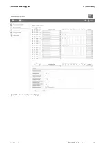
2. Select "
Status configuration
" in the context menu.
3. Search for the row with the status to be configured in the "
Status of the digital input ports
" column.
4. Put a tick in the "
active
" column next to the status to be configured.
☑ The status is active and will be evaluated by the Power Reducer Box upon saving.
5. In the "
Operating mode
" column, select the "
Cos phi setpoint
" of the status to be configured.
6. In the "
cos phi
" column of the status to be configured, enter the cos phi values for the line
conductors L1, L2 and L3.
The cos phi value can be between 0.10 and 1.00. Different line conductors are only interpreted
by inverters with multiple line conductors (see inverter manual). In the case of single-phase
inverters, enter the same value for all line conductors.
7. In the "
Excitation
" column, select whether the cos phi value is overexcited or underexcited.
8. Configure additional statuses in the same way.
9. Adopt the general settings of the system statuses (see Section 8.3.5 "Setting General System
10. Select [
Save
].
☑ The cos phi setpoint is set.
8.3.4 Configuring Combined Operating Modes
You can configure the following combined operating modes:
• "
Active power limitation and reactive power setpoint
"
• "
Active power limitation and Cos phi setpoint
"
Configuring combined operating modes
Note that for the combined operating modes, the respective settings must be defined in the
same way as the simple operating modes (see Section 8.3.1to 8.3.3). If you have any doubts,
contact SMA Solar Technology AG.


