6 Electrical Connection
SMA Solar Technology America LLC
Installation Manual
RSS-US-IA-xx-14
29
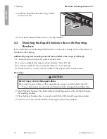
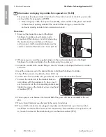
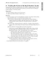
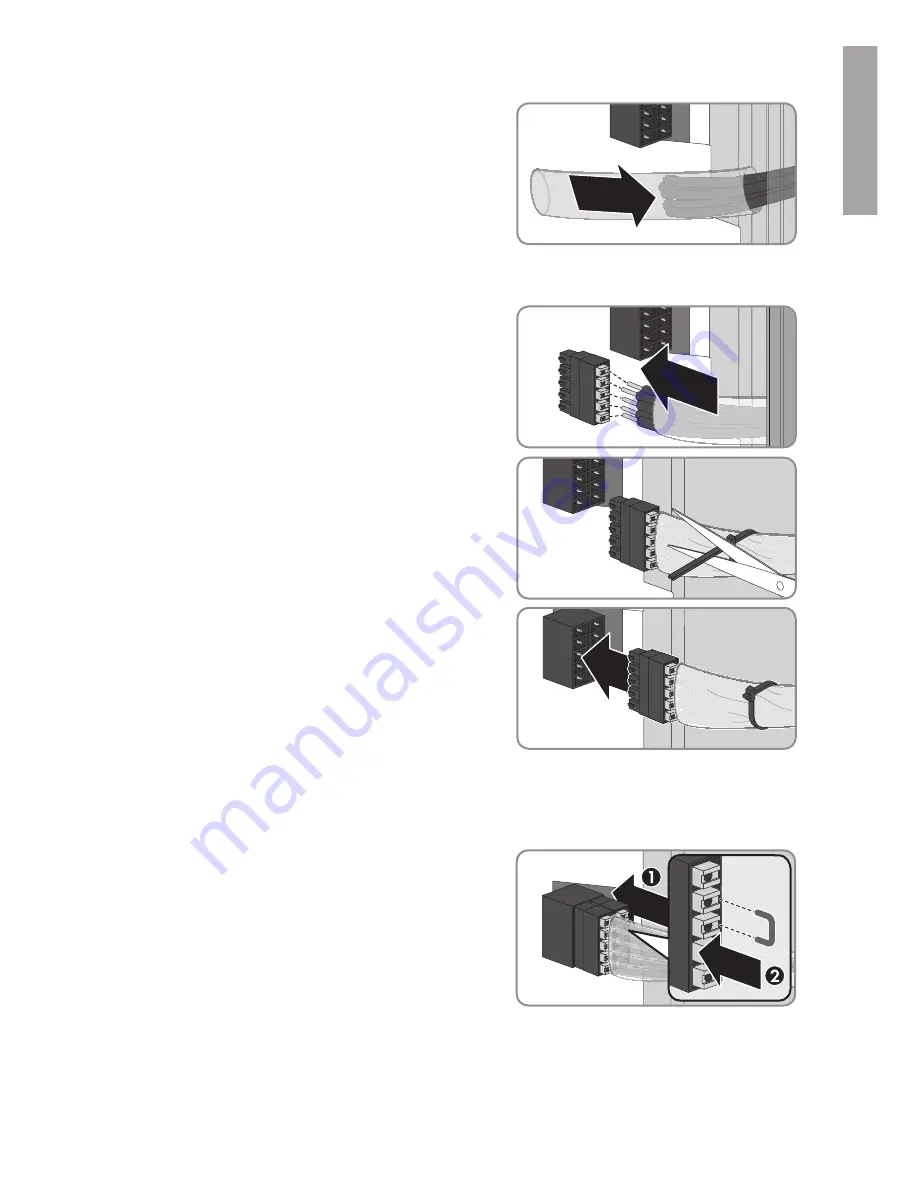
5. Lead a silicone tube over the conductors inside the
Rapid Shutdown Box.
6. Strip off the conductor insulation by 8 mm (0.31 in).
7. In the case of fine stranded wire, provide each conductor with a bootlace ferrule.
8. Connect the conductors to a five-pole plug. Observe
the pin assignment.
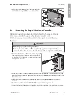
9. Place the cable tie onto the silicone tube, tighten
and cut off the projecting end of the cable tie. This
connects the conductors and the silicone tube
together securely.
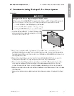
10. Plug the five-pole plug with the connected
conductors into the upper pin row of the terminal
block
RSC
.
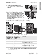
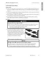
11. Connect the Rapid Shutdown Boxes together. To do so, connect the incoming conductors to a
plug and plug this into the lower pin row of the connecting terminal block
RSC
, and always
connect the outgoing conductors to a plug and plug this into the upper pin row of the terminal
block
RSC
.
12. In the last Rapid Shutdown Box, plug the second
five-pole plug into the lower pin row of the terminal
block
RSC
and place a jumper wire between pins 3
and 4. Here, use a jumper wire that is rated for the
maximum system voltages or insulate the jumper
wire using a piece of one of the supplied silicone
tubes.
ENGLISH
Summary of Contents for RSB-2S-US-10
Page 132: ...www SMA Solar com...


