background image

Summary of Contents for SB1100U

Page 1: ...Photovoltaic Grid Tied String Inverter Sunny Boy 1100U Installation Guide SOLARTECHNOLOGY...

Page 2: ......

Page 3: ...he exclusion of implied warranties may not apply in all cases under some statutes and thus the above exclusion may not apply Specifications are subject to change without notice Every attempt has been...

Page 4: ...and Hazard Symbols This symbol is used to call attention to important information that you must have when installing and or operating the Sunny Boy Failure to read and follow instructions marked with...

Page 5: ...ocal and National Electrical Code ANSI NFPA 70 The Sunny Boy contains no user serviceable parts Always return the unit to an SMA authorized Service Center for repairs and maintenance Before installing...

Page 6: ...use to ensure optimal operation of the system Example This symbol accompanies examples that are included to help you understand certain topics Warranty All Sunny Boy inverters sold in the USA have a f...

Page 7: ...e 3 5 4 Wiring and Connecting the Sunny Boy Sunny Boy 1100U Internal Components 4 2 Opening the Sunny Boy 1100U 4 2 Locating Internal Components 4 2 Wiring the AC Output 4 5 AC Connection Requirements...

Page 8: ...vi SMA America SB1100U 11 SE1604...

Page 9: ...esigned for use in grid tied PV generating plants It accepts DC voltage inputs from PV arrays of up to 400 V DC A grid feeding inverter takes the DC output of the PV array converts it to AC adjusts th...

Page 10: ...and Inspection This section provides instructions and information for unpacking the Sunny Boy inspecting it for shipping damage and if necessary returning a damaged Sunny Boy Section 3 Mounting the S...

Page 11: ...damage immediately to your SMA dealer and to the shipping company that delivered the Sunny Boy If it becomes necessary to return the Sunny Boy use the original packaging in which the Sunny Boy was de...

Page 12: ...Unpacking and Inspection 2 2 SMA America SB1100U 11 SE1604...

Page 13: ...caused by the sun can result in reduced output from the PV system When the heatsink on the top of the Sunny Boy is exposed to direct sunlight the inverter operates in Derate Mode which reduces the ou...

Page 14: ...e the installation it will eventually condense within the case and the moisture can damage the electronic components Do not install the Sunny Boy when it is raining and if possible choose a day when t...

Page 15: ...for heat dissipation above the Sunny Boy s heat sink In a normal operating environment with good ventilation eight inches of clearance is adequate However if the airflow to the Sunny Boy is restricte...

Page 16: ...Mounting the Sunny Boy Dimensions and Recommended Clearances 3 4 SMA America SB1100U 11 SE1604 Wall Mounting Bracket Figure 3 3 Dimensions of the wall mounting bracket...

Page 17: ...Boy 1100U with Mounting Bracket Use the following procedure to mount the Sunny Boy 1 Locate the T shaped wall mounting bracket included in the shipping container with the Sunny Boy 2 Position the wal...

Page 18: ...et and into the holes you drilled in the wall Tighten the screws until the bracket is held firmly against the wall see 1 in Figure 3 4 Do not over tighten the screws 6 Carefully lift the Sunny Boy int...

Page 19: ...carry the DC voltage from the PC array to the Sunny Boy in the order described in the procedures in this section Deviating from these procedures could expose you to hazardous voltages that can cause...

Page 20: ...rs for DC input AC output and communications are inside the Sunny Boy s case To gain access to these and other internal components you must remove the cover Opening the Sunny Boy 1100U Remove the four...

Page 21: ...ese internal AC and DC wiring terminals see Figure 4 1 accept a maximum wire size of 6 AWG Knockouts are provided on the bottom of the Sunny Boy near each of the terminals for the wires to enter the c...

Page 22: ...tom View of the Sunny Boy 1100U Showing 1 2 Wiring Knockouts CAUTION All knockouts in the Sunny Boy chassis are sized for 1 2 inch rigid conduit EMT DO NOT enlarge any of these holes as this is a viol...

Page 23: ...onnections to the Sunny Boy Voltage drop and other considerations may dictate that larger size wires be used WARNING The National Electrical Code NEC states that the inverter must be connected to a de...

Page 24: ...onnection See our web site for additional information Table 4 1 Voltage and Frequency Limits for the AC Connection Connecting the AC Wires Use the following procedure to connect the AC wires to the Su...

Page 25: ...ing knockout 5 Pull the AC wires through the conduit from the interior of the breaker box to the interior of the Sunny Boy Note Refer to Figure 4 4 on page 4 8 for steps 7 through 8 CAUTION Avoid usin...

Page 26: ...Wiring and Connecting the Sunny Boy Wiring the AC Output 4 8 SMA America SB1100U 11 SE1604 Figure 4 4 AC Connection Terminals...

Page 27: ...Requirements WARNING All electrical installations must be done in accordance with all local electrical codes and with the National Electrical Code NEC ANSI NFPA 70 Use 10 AWG minimum 90 C 194 F coppe...

Page 28: ...Wiring and Connecting the Sunny Boy Wiring the DC Input 4 10 SMA America SB1100U 11 SE1604 Figure 4 6 Online String Configuration Calculator at www sma america com...

Page 29: ...ystem and wait a minimum of 5 minutes for the Sunny Boy to completely discharge before connecting any wires to the Sunny Boy or disconnecting any wires from the Sunny Boy Failure to turn OFF all break...

Page 30: ...ure 4 6 To navigate to the string sizing calculator click String Sizing in the menu bar on the right side of the page on page 4 9 Use the following procedure to connect the DC wires to the Sunny Boy 1...

Page 31: ...ions for either one or two PV strings The positive and negative terminal blocks each have two positions so two pairs of DC input wires can be connected in parallel CAUTION Avoid using wire nuts to joi...

Page 32: ...nger than 15 meters 49 2 ft with a minimum of two pairs of 24 AWG wires A cable of this type with a serial connector at one end is available from SMA America Connecting an RS 232 Cable Use the followi...

Page 33: ...232 Cable Communication Terminal Block Sunny Boy Signal Name 9 Pin Serial Port Connector PC 25 pin Serial Port Connector PC Case Shield Case Case 2 RxD Output from Sunny Boy 2 3 3 TxD Input to Sunny B...

Page 34: ...Use the following procedure to install an RS 485 data communication cable Note The following steps describe how to connect one Sunny Boy inverter to an RS 485 bus For information on connecting more th...

Page 35: ...and Connecting the Sunny Boy Connecting Communication Cables SB1100U 11 SE1604 SMA America 4 17 Figure 4 9 Detail of RS 485 Termination and Jumper Settings RS 485 Pinouts 2 A Data 7 B Data 5 SR Signa...

Page 36: ...ll four screws and lock washers are required to ensure that the cover is grounded properly and is fully sealed to the case Handle the cover carefully as even minor damage to the cover could result in...

Page 37: ...olding the cover in place carefully insert the four screws with lock washers through the holes in the cover into the threaded holes in the case and turn them in until they are finger tight Be careful...

Page 38: ...Wiring and Connecting the Sunny Boy Connecting Communication Cables 4 20 SMA America SB1100U 11 SE1604...

Page 39: ...thing comes in contact with the heat sink and that surrounding materials are sufficiently heat resistant WARNING Follow the steps in the commissioning pro cedure in the order they are presented Deviat...

Page 40: ...ty breaker box 3 Remove the opaque covering from the PV array 4 Close the DC disconnect in the DC disconnect enclosure If sufficient irradiance is present the PV array produces adequate DC power for t...

Page 41: ...on the bottom of the Sunny Boy 7 Close the DC disconnect in the DC disconnect enclosure 8 If all of the problems have been resolved the Sunny Boy switches to normal fully automatic operation indicated...

Page 42: ...5 4 SMA America SB1100U 11 SE1604 Figure 5 1 Commissioning Flowchart for the Sunny Boy 1100U If the Sunny Boy is not operating as expected after the commissioning procedure is complete refer to Secti...

Page 43: ...inimal internal DC power consumption The maximum power the Sunny Boy 1100U will consume in normal operation is 4W Note Since the Sunny Boy operates from the power produced by the PV array you must tak...

Page 44: ...Commissioning the Sunny Boy 5 6 SMA America SB1100U 11 SE1604...

Page 45: ...DI fuse located in the holder on the underside of the inverter is defective The yellow LED indicates that there is a fault of some kind either inside the inverter itself or somewhere in the system and...

Page 46: ...Displays and Messages 6 2 SMA America SB1100U 11 SE1604 Figure 6 1 The Sunny Boy LED Status Indicator...

Page 47: ...from the array is sufficient to operate the control but not yet powerful enough to begin feeding the grid Data transmission is not possible during initialization Occasionally during inclimate weather...

Page 48: ...than 10 seconds and then the inverter resumes normal operation This status can also be adjusted manually operating mode Stop Waiting The inverter has determined that there is enough power from the ar...

Page 49: ...e voltage with the highest output power Constant Voltage Mode The voltage from the PV array has been set to a fixed value This value is set by using the Sunny Boy Control or the Sunny Data software Th...

Page 50: ...reset manually The inverter will not restart automatically Defective GFDI Fuse The GFDI fuse located in the fuse holder on the bottom of the inverter is defective If the fuse has blown due to a ground...

Page 51: ...yellow LED remains lit The Sunny Boy has detected a fault with the internal utility monitoring system When the inverter detects a fault of this kind it will no longer connect to the utility grid To c...

Page 52: ...e Vac Max Low Grid Frequency fac Min High Grid Frequency fac Max Significant change in grid frequency Check the condition of the grid by varifying service to other customers or to other equipment Also...

Page 53: ...condition remains the code will continue to be sent The inverter has detected a grid impedance value that is too high for safe operation If this condition occurrs often the actual grid impedance can...

Page 54: ...nks 4 times The code is repeated 3 times If the condition remains the code will continue to be sent The inverter has detected an input voltage that is too high for safe operation WARNING Disconnect th...

Page 55: ...seconds and then blinks 5 times The code is repeated 3 times If the condition remains the code will continue to be sent The inverter has encountered a condition that makes it impossible to return to n...

Page 56: ...nt using the electrical wiring in the building as transmission lines RS 232 Data from one inverter is sent via RS 232 cable to a remote control unit or PC Maximum length of cable is 50 15 m RS 485 Dat...

Page 57: ...Messages of the Sunny Display During Initialization The following messages are displayed during initialization of the inverter The installed firmware versions of the control system BFR and the curren...

Page 58: ...ts from the beginning again First the E Today total energy produced on this day is displayed together with the current operating status The message is followed by the current power and the current PV...

Page 59: ...ure for 5 seconds Failures that result from a specific value that e g exceeds a limiting are specified with the value that caused the failure as well as the current value The normal operating data is...

Page 60: ...ound illumination and the display shown on the side WARNING Disconnect the inverter from the supply voltage immediately otherwise it can be severely damaged Check the input voltage and your module con...

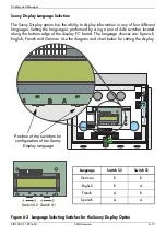
Page 61: ...a pair of slide switches located along the bottom edge of the display PC board The language choices are Spanish English French and German Use the diagram and chart below for setting the display Figur...

Page 62: ...SRR Stromregelungsrechner Current Control System Measuring Channels Vpv PV input voltage Vpv Setpoint desired input voltage of the Vpv control Iac current to the grid Vac grid voltage Fac grid frequen...

Page 63: ...hecking grid grid impedance MPP Search PV voltage is determined and set MPP Sunny Boy is in MPP mode V Const Sunny Boy is in constant voltage mode Derating reduction of the grid feeding power Disturba...

Page 64: ...ic grid is down and disconnects from the grid in order to avoid islanding Check the grid frequency and the grid cable connection in the Sunny Boy enclosure If the grid frequency is out of range due to...

Page 65: ...value MSD UAC MSD VAC MSD FAC MSD ZAC Internal measurement comparison error The Sunny Boy measured values of BFR and SRR are too different from each other K1 Close K1 Open Relay test failed EEPROM Tr...

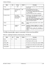
Page 66: ...etpoint voltage for constant voltage operation These parameters only are important in case the parameter Operating Mode is set to V const Vac Min V 180 300 213 Lower Vac Min and upper Vac Max limit of...

Page 67: ...user level to default values Reset errors Resets all permanent device disable dBh and the failure EarthCurMax occurs To remove this failure follow the steps in Section 5 Commissioning the Sunny Boy D...

Page 68: ...Displays and Messages 6 24 SMA America SB1100U 11 SE1604...

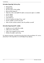
Page 69: ...6 Check and record the exact Mode and Error messages on the LCD display or other communication system if installed Take appropriate action to correct the issue If necessary check the DC and AC voltage...

Page 70: ...Check GFDI Fuse Can you reproduce the failure If yes how Has this problem occurred in the past What were the ambient conditions when the problem occurred Information Regarding the PV modules Manufactu...

Page 71: ...n accordance with the instructions may cause harmful interference to radio communications However there is no guarantee that interference will not occur in a particular installation If this equipment...

Page 72: ...Troubleshooting 7 4 SMA America SB1100U 11 SE1604...

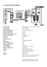
Page 73: ...or Unity Peak Inverter Efficiency 93 Cooling Convection cooling no fan PV Start Voltage 180 V DC Maximum AC Output Current 4 6 A Maximum DC Input Current 9 5 A DC Votage Ripple Less than 10 Power Cons...

Page 74: ......

Page 75: ......

Page 76: ......

Reviews: