SMA America, LLC
Electrical connection
Installation Guide
SBCBTLUS-IUS094510
25
6.5 Connecting the inverter
Route the cables of the combined screw terminal to the inverter along the raceway printed on the
board (see figure on page 20).
Consider the required cable sizes and torques. Refer to 11.1 ”Cable requirements” (page 33).
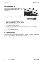
6.5.1 Connecting DC+
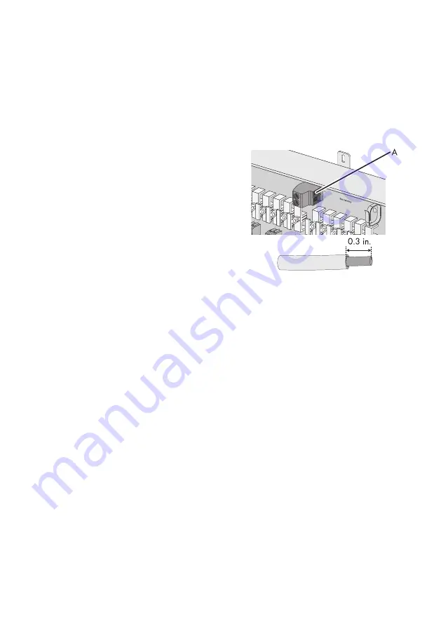
Connect the DC+ conductors of the DC inverter/
disconnect at the inverter to the "Combined Out+" screw
terminals (A).
1. Strip the cable by approx. 0.3 in. (8 mm)
2. Open the screw terminals completely by turning
them counterclockwise with a flat-head screwdriver.
3. Plug the stripped cable into the screw terminal.
4. Tighten the screw terminal clockwise.
☑ DC+ of the inverter is connected.

