3 Disconnecting and Reconnecting
SMA Solar Technology AG
Service Manual for Installers
11
SC-UP_SCS-UP_EZE-SG-en-10
3
Disconnecting and Reconnecting
3.1
Disconnecting the Inverter
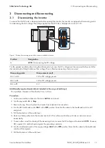
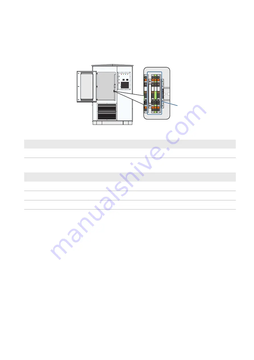
To ensure that the DC side is de-energized before opening the inverter, the inverter is equipped with measuring points
for determining the DC voltage. The voltage applied on the DC side is displayed in a ratio of 1:10.
A
−X 252
DC+
PE DC-
−X 251
DC+
PE DC-
Figure 1: Position of measuring points in the customer installation location
Position
Designation
A
-X251
for measuring the PV voltage
For the greatest possible safety during the disconnection process, the DC voltage must be measured before and after
disconnecting the String-Combiners from voltage. Thus, a flawless measuring chain is ensured.
Measuring points
Measurement result
DC+ to DC-
10% of PV voltage present
DC+ to PE
10% of PV voltage present
DC- to PE
0 V
Additionally required material (not included in the scope of delivery):
☐ 2 padlocks. Diameter of the shackle: 5 mm to 8 mm.
Procedure:
1. On the user interface make sure that error
6494
is not present .
2. Turn the key switch
-S1
to
Stop
.
3. Remove the key. This will protect the inverter from inadvertent reconnection.
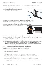
4. Turn the DC load-break switch
-Q61
to the
OFF
position. Note that the cable to the load-break switch is still
energized.
5. Pull the bracket out of the switch lever.
6. Hook a suitable padlock into the bracket and lock it. This will ensure that the switch lever cannot reconnect
inadvertently.
7. To ensure the correct functioning of the measuring chain, measure the DC voltage at the terminal
-X251
. Measure
DC+ against DC- and both poles against the grounding conductor.
8. Turn the load-break switch of the supply voltage
-Q62
to the
OFF
position. Note that the cable to the load-break
switch is still energized.
9. Pull the bracket out of the switch lever.
Summary of Contents for SC 4000 UP
Page 20: ...www SMA Solar com...


