3 Disconnecting and Reconnecting
SMA Solar Technology AG
Service Manual for Installers
13
SC-UP_SCS-UP_EZE-SG-en-10
6. Attach magnetic signs indicating the name of the duly authorized person to the transformer panel.
7. Connect the grounding- and short-circuiting equipment to the AC busbars between the inverter and medium-
voltage transformer.
8. Disconnect any additional external voltage.
9. Cover or isolate any adjacent live components.
3.3
Reconnecting the Medium-Voltage Transformer
Connecting and disconnecting medium voltage
Only a duly authorized person trained in electrical safety is allowed to connect and disconnect the medium
voltage.
Requirements:
☐ The protective cover that protects the low-voltage area between the inverter and the MV transformer must be
mounted.
☐ The cover at the medium-voltage connection area on the MV Transformer must be mounted.
Procedure:
1. Remove the grounding- and short-circuiting equipment from the AC busbars between the inverter and MV
transformer.
2. Remove the magnetic signs indicating the name of the duly authorized person from the circuit breaker panel and
the "Do not operate!" magnetic sign. varistor.
3. Remove the padlock from the circuit breaker for the MV switchgear.
4. Open the grounding switch at the transformer panel of the MV switchgear.
5. Close the circuit breaker for the transformer panel of the MV switchgear.
6. Restart the inverter (see Section 3.4, page 13).
3.4
Reconnecting the Inverter
DANGER
Danger to life due to electric shock when live components are touched
High voltages are present in the live parts of the product. Touching live parts will result in death or serious injury due
to electric shock.
• Before reconnecting, make sure that the panels are mounted Disassembling and Mounting the Panels.
• Before reconnecting, make sure that the protective covers are mounted.
• Before reconnecting, make sure that the hatches are closed Opening and Closing the Hatches.
Procedure:
1. Actuate upstream switchpoint. Insert fuses in the String-Combiners or switch on the circuit breakers of the String-
Combiners.
2. Switch on the disconnection unit of the battery.
3. Ensure that the panel is mounted in front of the AC disconnection unit.
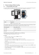
4. Remove the padlocks from the brackets of the DC switches
-Q61
and
-Q62
.
5. Turn the DC load-break switch
-Q62
to the
ON
position.
6. Turn the DC load-break switch
-Q61
to the
ON
position.
7. Turn the key switch
-S1
to
Start
.
Summary of Contents for SC 4000 UP
Page 20: ...www SMA Solar com...

