background image

10  Contact

SMA America, LLC

50

SCCP-US-WH-US_en-31

Maintenance Manual

10 Contact

If you have technical problems concerning our products, contact the SMA Service Line. We require the following 

information in order to provide you with the necessary assistance:

• Device type
• Serial number
• Type and number of modules connected
• Communication type
• Error number and error message

United States/

Estados Unidos

SMA America, LLC
Rocklin, CA

+1 877-MY-SMATech (+1 877-697-6283)*
+1 916 625-0870**

* toll free for USA, Canada and Puerto Rico / Llamada gratuita en EE. UU., Canadá y Puerto Rico

** international / internacional

Canada/

Canadá

SMA Canada, Inc.
Toronto

+1 877-MY-SMATech (+1 877-697-6283)***

*** toll free for Canada / gratuit pour le Canada

Summary of Contents for SC 500CP-US-10

Page 1: ...SCCP US WH US_en 31 98 123900 01 Version 3 1 AMERICAN ENGLISH Maintenance Manual SUNNY CENTRAL 500CP US CA 500CP US CA 600V 630CP US CA 720CP US CA 750CP US CA 800CP US CA 850CP US CA 900CP US CA...

Page 2: ...without notice Every attempt has been made to make this document complete accurate and up to date Readers are cautioned however that SMA America LLC and SMA Solar Technology Canada Inc reserve the ri...

Page 3: ...ed when installing and or operating the product To reduce the risk of personal injury and to ensure the safe installation and operation of the product you must carefully read and follow all instructio...

Page 4: ...ollow all safety precautions and instructions as described in the documentation 51 1 All electrical installations must be made in accordance with the local and National Electrical Code ANSI NFPA 70 or...

Page 5: ...rvals 20 4 2 Spare Parts 21 5 Maintenance with DC AC and Control Voltage Present 21 5 1 Reading the Replacement Interval Meter 21 5 2 Reading Error Messages and Warnings 21 5 3 Checking the DC Contact...

Page 6: ...Stops and Hinges 42 7 12 Checking the Switch Cabinet for Corrosion 42 7 13 Mounting the Panels 43 8 Connecting the Control Voltage 44 9 Maintenance when Control Voltage is Present 45 9 1 Safety 45 9 2...

Page 7: ...ified persons have been trained in how to deal with the dangers and risks associated with installing electrical installations and possess all the necessary knowledge for averting danger Qualified pers...

Page 8: ...raphy Usage Example bold Display messages Elements on a user interface Parameters Terminals Slots Elements to be selected Elements to be entered Select the parameter ExlTrfErrEna and set to Off Select...

Page 9: ...e following table you will find the full designation and an explanation where applicable Abbreviations Designation Explanation AC Alternating Current DC Direct Current GFDI Ground Fault Detection Inte...

Page 10: ...tings impedance and the resultant effects on the utility interconnection performance of the inverter with respect to the ratings and impedance of the transformer selected The inverter has not been eva...

Page 11: ...the inverter Unauthorized persons may not operate the inverter and must keep at a distance from the inverter No reconstruction modification or installation of additional components may be carried out...

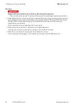
Page 12: ...t least 15 minutes for the capacitors of the Sunny Central to discharge completely Always check that no voltage is present in any of the components before working on the inverter Ground and short circ...

Page 13: ...ents can result in death or serious injury due to electric shock Always close and lock the inverter Remove the keys from the door locks and from the key switch Keep the keys in a safe place Ensure tha...

Page 14: ...maintain the inverter when the environment is dry and free of dust Do not operate the inverter while the door is open If present connect the external supply voltage after having set up and installed t...

Page 15: ...dance with NEMA NFPA 70E Table 130 7 C 16 2 4 Symbols on the inverter Hazard Risk Category 2 protective equipment required In accordance to NFPA 70E an arc flash hazard risk analysis has been performe...

Page 16: ...AC side With the Integrated DC Switch the inverter can be disconnected from the PV array If the inverter does not have an Integrated DC Switch a Disconnect Unit must be installed between the inverter...

Page 17: ...ility grid Circuit breaker The unit is provided with a UL listed circuit breaker on the output rated 1 600 A for branch circuit protection If the circuit breaker shall be located externally to secure...

Page 18: ...ype label includes the following information Device type Serial number Serial No Production version Fabrication version Production date Fabrication date Device specific data Position Designation A Inv...

Page 19: ...product must be carried out by qualified persons only Risk of burns due to hot surfaces The product can get hot during operation Avoid contact during operation Allow the product to cool down sufficien...

Page 20: ...nce Every 24 months AC circuit breaker Functional test Cleaning Checking the contact elements See the manufacturer s maintenance manual of the AC circuit breaker Every 24 months Description Interval 2...

Page 21: ...value CntGfdiSw Number of switching cycles of the Integrated DC Switch in the instantaneous value CntDCSw If the corresponding instantaneous value equals or is greater than the replacement interval of...

Page 22: ...r to Stop By doing so the DC contactor is audibly switched off 2 Open the doors of the interface cabinet 3 Check the switching state of the DC contactor The DC contactor is switched off The DC contact...

Page 23: ...ing the AC Circuit Breaker Figure 6 Switch and position displays of the AC circuit breaker 1 5 Electric shock due to live voltage High voltages are present in the inverter and its components Some main...

Page 24: ...vice approved by the manufacturer of the AC circuit breaker e g TT1 from ABB Procedure 1 Open the doors of the interface cabinet 2 Use the testing device to check whether the AC circuit breaker is rea...

Page 25: ...for the capacitors of the Sunny Central to discharge completely Always check that no voltage is present in any of the components before working on the inverter Ground and short circuit the device Cove...

Page 26: ...e AC contactor and the DC switch are open Touching live components of this assembly will result in death or serious injury Do not touch live components Do not remove protective covers Observe the warn...

Page 27: ...n distribution or sub distribution 8 If an internal AC Disconnect is present open the flap of the AC Disconnect and switch the AC Disconnect off 9 Disconnect the external supply voltage externally 10...

Page 28: ...Use a suitable tool or safety gloves 7 Maintenance in Disconnected State 7 1 Safety 1 5 Danger to life due to electric shock High voltages that can result in lethal electrical shocks are present in th...

Page 29: ...ates The panels are connected to the inverter via grounding straps 1 1 5 Danger to life due to electric shock or electric arc by touching live components Disconnect the inverter and wait 15 minutes un...

Page 30: ...ion plate and apply an upward pressure in the middle 6 Mount the panels see Section 7 13 7 4 Cleaning the Air Duct and Insect Screens 1 1 5 Danger to life due to electric shock or electric arc by touc...

Page 31: ...emove the screws of the left hand insect screen Use an Allen key for this 5 Pull the bottom of the left hand insect screen forward This removes the insect screen 6 Vacuum the air duct from the outside...

Page 32: ...ens are not damaged Are the insect screens damaged Replace the damaged insect screens 9 Insert the right hand insect screen 10 Screw the right hand insect screen in place Use an Allen key for this Tor...

Page 33: ...gs for discoloration and signs of wear If the fuses or tension springs are discolored or show signs of wear replace them 5 Check the insulation and terminals for discoloration and signs of wear If the...

Page 34: ...ng device documentation 4 Check whether the ready indicator of one of the surge arresters is red If the ready indicator of one of the surge arresters is red replace the surge arrester Remove the cable...

Page 35: ...f the power cabling 05 Damage to screw connections from over tightening Only tighten loose connections applying the prescribed torque Torque specifications are shown in the installation manual of the...

Page 36: ...comparisons on an annual basis If screw connections are loose tighten them with a torque wrench 3 Check insulation and connections for discoloration and changed appearance If insulation and connection...

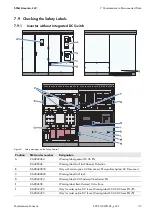
Page 37: ...arning label general SC US EN 86 430042 Warning label Arc Flash Hazard Protection B 86 00480030 Only with order option AC Disconnect Photovoltaic System AC Disconnect C 86 00480020 Warning label Arc F...

Page 38: ...erminal N 86 10867027 For negative grounding or insulated 1 000 V PV 86 430045 For negative grounding or insulated 600 V PV 86 10867028 For positive grounding or insulated 1 000 V PV 86 430044 For pos...

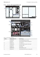
Page 39: ...verter Position SMA Bestellnummer Bezeichnung A 86 0043464 Warning label general SC US EN 86 430042 Warning label Arc Flash Hazard Protection B 86 0033325 Label Closed C 86 00480030 Label Photovoltaic...

Page 40: ...ge P 86 10867027 For positive grounding 1 000 V PV 86 430045 For positive grounding 600 V PV 86 10867028 For negative grounding 1 000 V PV 86 430044 For negative grounding 600 V PV Q 86 0043462 ABC 60...

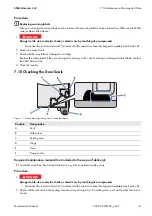
Page 41: ...x Procedure 2 Check whether the seals in the sealing area show any damage Tip the sealing area is not visible when the door is closed Replacing warning labels Missing or damaged warning labels must be...

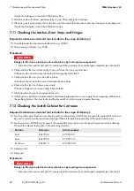
Page 42: ...installed in regions where below freezing temperatures occur apply the non greasing antifreeze to the profile cylinder of the door locks and the key switch in order to protect against freezing 7 12 Ch...

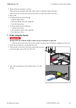
Page 43: ...a with a degreaser Paint the affected area 5 To remove large area surface damage Sand the entire surface Clean the entire surface with a degreaser Paint the entire surface 7 13 Mounting the Panels 2 C...

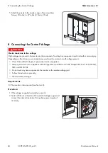
Page 44: ...e internal transformer for auxiliary power supply if necessary 1 5 Electric shock due to live voltage High voltages are present in the inverter and its components Touching live components results in d...

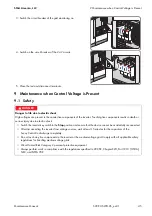
Page 45: ...results in death or serious injury due to electric shock Switch the inverter key switch to the Stop position and ensure that the device cannot be accidentally reconnected After disconnecting the inver...

Page 46: ...esent in the inverter and its components Touching live components results in death or serious injury Depending on the function some maintenance work must be carried out with voltage present Wear Hazar...

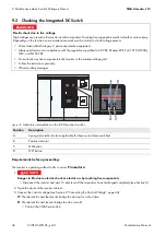
Page 47: ...r of the DC load break switches are not indicating the Off position contact the SMA Service Line 6 Close the doors of the interface cabinet 7 Switch the key switch of the inverter to Start 8 Check whe...

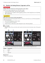
Page 48: ...protective equipment Always perform work in compliance with the regulations specified in 29 CFR Chapter XVII Part 1910 OSHA NEC and NFPA 70E 87 21 Risk of burns due to hot parts of the heating elemen...

Page 49: ...ted correctly if the relay of the hygrostat emits an audible click 5 Check whether the heating element is beginning to radiate heat after approx five minutes If the heating element does not radiate he...

Page 50: ...tance Device type Serial number Type and number of modules connected Communication type Error number and error message United States Estados Unidos SMA America LLC Rocklin CA 1 877 MY SMATech 1 877 69...

Page 51: ......

Page 52: ...www SMA Solar com SMA Solar Technology...

Reviews: