background image

SMA Solar Technology AG

Battery management

Technical Description

SI5048-TEN093630

99

13.5 Battery Preservation Mode

The Sunny Island has a sophisticated battery preservation mode. The battery preservation mode 
prevents deep discharge from the battery as far as possible when the energy supply is low, thus 
preventing a total system failure as well as damage to the battery.
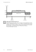
The battery preservation mode has three levels that are activated as a result of the state of charge 
(when the charge drops below the respective limit, parameters "223.05 BatPro1Soc", "223.06 
BatPro2Soc" and "223.07 BatPro3Soc"):

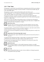
Level 1:

 The first level is used to switch the Sunny Island into standby mode at times when the energy 

is not necessarily required (e.g., at night). You define the start time using the "223.01 BatPro1TmStr" 
parameter and define the stop time using the "223.02 BatPro1TmStp" parameter.

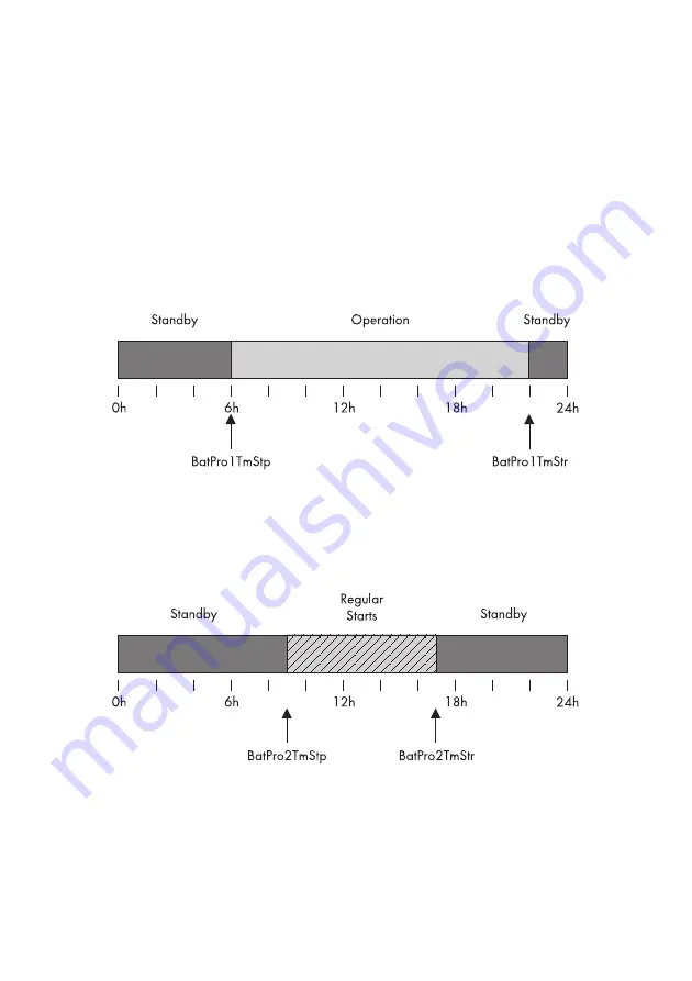
Level 2:

 The second level of the battery preservation mode ensures that the Sunny Island is started 

regularly every two hours only in the time period during which energy supply is expected, and that it 
attempts to charge the battery from the AC side. In case of PV systems this time is during the day. 
In this case, you define the start time using the "223.03 BatPro2TmStr" parameter and the stop time 
using the "223.04 BatPro2TmStp" parameter.

Level 3: 

The third level ensures that the battery is protected from deep discharge and thus against 

damage. In this case, the Sunny Island is switched off completely. To start it, see section 
9.5 ”Reactivating the Device Following Automatic Shutdown” (page 63).
At all three levels, the Sunny Island is stopped only if no battery current flows within 6 minutes 
(limit 3 A charging current).

Summary of Contents for SI 5048

Page 1: ...SI5048 TEN093630 TBE SI5048 Version 3 0 EN Off grid Inverter SUNNY ISLAND 5048 Technical Description...

Page 2: ......

Page 3: ...2 3 Scope of delivery 19 2 4 Identifying the Sunny Island 20 3 Safety Precautions 21 3 1 Important Notes Regarding Operation 21 3 2 Potential Hazards 22 4 Mounting the Device 23 4 1 Selecting the Moun...

Page 4: ...4 4 Multi function Relays 1 and 2 44 6 4 5 BatVtgOut Power Supply 47 6 4 6 DigIn Digital Input 48 6 5 Interface for External Communication 49 6 5 1 Connection of the Interface 49 7 Control Elements 51...

Page 5: ...ay Messages Overview 74 10 7 Parameter Display 78 10 8 Display of Events 78 10 9 Display of Warnings and Failures 79 11 Archiving Data on an SD Card 80 11 1 Inserting the Card 83 11 2 Removing the Car...

Page 6: ...reservation Mode 99 13 6 Battery Diagnostics 100 13 7 Battery Lead Resistance 101 14 Connecting External Sources 102 14 1 Generator 102 14 1 1 Connection in Parallel 103 14 1 2 Generator Start Options...

Page 7: ...on Startup 129 16 3 2 Stopping and Deactivating 129 16 4 Generator Operation 130 16 5 Behavior with Different Charge States 130 16 6 Communication Test 131 16 7 Automatic Frequency Adjustment AFRA 131...

Page 8: ...Charge Controller 140 145 19 2 Adjustable parameters 147 19 2 1 Inverter Settings 210 147 19 2 2 Battery Settings 220 148 19 2 3 External Settings 230 152 19 2 4 Relay Settings 240 160 19 2 5 System S...

Page 9: ...gory INV 186 20 6 2 Category BAT 187 20 6 3 Category GEN 187 20 6 4 Category GRD 187 20 6 5 Category REL 188 20 6 6 Category SYS 189 20 7 Error Categories 190 20 8 Warnings and Fault Indications 191 2...

Page 10: ...Table of Contents SMA Solar Technology AG 10 SI5048 TEN093630 Technical Description...

Page 11: ...and later 1 2 Target Group This manual is exclusively for qualified personnel The tasks described in this manual may only be performed by qualified personnel 1 3 Additional Information You will find f...

Page 12: ...ury WARNING WARNING indicates a hazardous situation which if not avoided could result in death or serious injury CAUTION CAUTION indicates a hazardous situation which if not avoided could result in mi...

Page 13: ...battery capacity possible which also means that smaller and thus more cost effective batteries can be used without affecting performance In order to prevent premature aging caused by incorrect chargi...

Page 14: ...The Sunny Island 5048 SMA Solar Technology AG 14 SI5048 TEN093630 Technical Description Components of a Sunny Island System...

Page 15: ...SMA Solar Technology AG The Sunny Island 5048 Technical Description SI5048 TEN093630 15 Single phase and Single phase parallel system...

Page 16: ...The Sunny Island 5048 SMA Solar Technology AG 16 SI5048 TEN093630 Technical Description Three phase system cluster 120...

Page 17: ...Solar Technology AG The Sunny Island 5048 Technical Description SI5048 TEN093630 17 2 2 At a glance The following figure provides an overview of all control elements and connections of the Sunny Isla...

Page 18: ...I5048 TEN093630 Technical Description Position Description A Display B LEDs showing device operation C Control buttons D Slot for the SD card E Connection area for additional connections F DC connecti...

Page 19: ...or if there are parts missing in the delivery Position Quantity Description A 1 Sunny Island B 2 Air grills C 1 Wall mounting bracket D 1 Battery temperature sensor E 1 Technical Description F 1 Docum...

Page 20: ...s on the right side of the enclosure O 2 3 pole print terminal for the connection of relays 1 and 2 P 2 M6x10 mm hexagon socket screw to attach the Sunny Island to the wall mounting bracket Q 2 M6 con...

Page 21: ...ue to parallel connection of different types of tension Always employ Sunny Islands of the same type within a system Never operate with different tension types in parallel Connection Requirements Be s...

Page 22: ...e to high voltages in the stand alone grid Death or serious injuries The Sunny Island can start on its own Before working on the stand alone grid disconnect all AC and DC power sources DANGER Death ha...

Page 23: ...ot mount the Sunny Island on flammable construction materials Do not mount the Sunny Island near highly flammable materials Do not mount the Sunny Island in potentially explosive areas CAUTION Risk of...

Page 24: ...nt in a horizontal position The connection area may not point upwards In a living area do not mount the unit on plasterboard walls etc in order to avoid audible vibrations The Sunny Island can make no...

Page 25: ...Mark the position of the drill holes using the wall mounting bracket and drill the holes Use 2 to 4 of the 6 holes in the middle of the wall mounting bracket CAUTION Risk of injury due to the Sunny I...

Page 26: ...ket using the opening in its rear for this purpose 4 Screw the Sunny Island to the wall mounting bracket on both sides using the screws M6x8 provided Only tighten the screws by hand The Sunny Island i...

Page 27: ...rk 5 1 Opening the Sunny Island 1 Stop the Sunny Island as described in section 9 2 Stopping the Sunny Island Standby page 61 2 Disconnect the Sunny Island from voltage sources as described in chapter...

Page 28: ...in the order shown on the right hand side The toothing of the washers must face toward the enclosure lid 2 Commission the Sunny Island as described in section 9 1 Activation page 60 The Sunny Island...

Page 29: ...able screw connections to fasten the cables inside the Sunny Island enclosure in a manner conforming to the appropriate standards The metric thread cable screw connections guarantee a dust free and wa...

Page 30: ...al fuse DC side and the material used in the grounding conductor The required cross section of a copper grounding conductor can be calculated using the following formula Trigger times for short circui...

Page 31: ...le feed through from the right Introduce the cable screw connection with the thread in the cable feed through Screw the counter nut onto the cable screw connection thread on the inside of the housing...

Page 32: ...ttery cable The current flowing through the battery cable causes a power loss and a drop in voltage with every meter of simple battery cable You can use the following table to find the power loss and...

Page 33: ...and a DC connection available for each ring cable lug max 70 mm for the battery feed cables in the Sunny Island DANGER Risk of lethal electric shock Death or serious burns If no external cable protec...

Page 34: ...th the thread in the cable feed through Screw the counter nut onto the cable screw connection thread on the inside of the housing and tighten 5 Attach the DC cable with the ring cable lug to the DC co...

Page 35: ...uit breakers of maximum 16 A and with a type B trigger characteristic If there is a short circuit the Sunny Island can trigger this circuit breaker If larger fuses or fuses that blow more slowly are u...

Page 36: ...onto the AC1 Loads Sunny Boys cable feed through Introduce the cable screw connection with the thread in the cable feed through Screw the counter nut onto the cable screw connection thread on the ins...

Page 37: ...ntroduce the cable screw connection with the thread in the cable feed through Screw the counter nut onto the cable screw connection thread on the inside of the enclosure and tighten 3 Remove the prote...

Page 38: ...e temperature Further information is provided in section 13 4 Charge control page 94 A battery temperature sensor must be connected in order to operate the battery temperature sensors included in the...

Page 39: ...ction of the 4 pole print terminal included in the delivery 4 Tighten the terminals 5 Insert the 4 pole print terminal into the BatTmp socket on the Sunny Island 6 Attach the battery temperature senso...

Page 40: ...ate additional DC generators and DC loads in your off grid system Only one battery current sensor connected to the respective master is required for a cluster NOTICE Damage to the battery due to the c...

Page 41: ...is double insulated and that the wire melts but the insulation remains intact in the event of a short circuit In addition the cable is not combustible In order to avoid measuring errors make sure to u...

Page 42: ...3 Remove the terminating resistor from the ComSyncOut socket of the master and plug it into the CompSyncIn socket of the master 4 Plug the RJ45 cable into the ComSyncOut socket 5 Connect the Sunny Is...

Page 43: ...SMA Solar Technology AG Electrical Connection Technical Description SI5048 TEN093630 43...

Page 44: ...he using the 241 01 Rly1Op and 241 02 Rly2Op parameters see chapter 15 Relays page 123 We recommend connecting the load shedding and generator request functions to the master since if a failure occurs...

Page 45: ...e corresponding wires to the 3 pole print terminals included in the delivery The pins have the following meaning NC Normally closed closed when idle C Contact operating contact NO Normally opened open...

Page 46: ...achieve safe operation of the system even in cases of low energy generation or very high consumption Disconnect only the loads never disconnect the generators e g PV inverters Installing the Power Su...

Page 47: ...A Depending on the internal temperature of the Sunny Island the triggering threshold is at over 0 6 A This connection can be used for example to supply a DC contactor for load shedding For connection...

Page 48: ...d the cable with cable end sleeves through the hole in the Sunny Island 3 Connect the cables correspondingly to the DigIn connection of the 4 pole print terminal included in the delivery 4 Tighten the...

Page 49: ...socket 4 Place the plug around the cable 5 Reinsert the plug in the opening provided in the rubber terminal area 6 Lay the cable in area C 7 Connect the cable Assignment pins in the RJ45 socket 8 The...

Page 50: ...d at different data transmission rates to communicate with external devices The parameter 250 06 ComBaud must be set correspondingly Position Description A Slot for communication interface B Sliding s...

Page 51: ...ontrol Elements In order to commission the Sunny Island you should familiarize yourself with its operation beforehand The individual control elements can be seen in the following figure Position Descr...

Page 52: ...it Breaker The DC circuit breaker is used to switch on off as well as disconnect the Sunny Island on the DC side For details see section 9 Activation and Deactivation page 60 Position Description A Ou...

Page 53: ...dating firmware and as a service interface For details see section 11 Archiving Data on an SD Card page 80 Button Function cancels the selected function answers NO navigates one menu level higher stop...

Page 54: ...use the menu to select the right system for you The display then shows a selection via which the parameters can be set specifically Check the connections Before starting the commissioning process make...

Page 55: ...s The QCG is started Start System if you have accidentally accessed the QCG and only would like to restart the system Occurrence of an error If the Sunny Island displays an error message unexpectedly...

Page 56: ...NiCd default setting 48 0 V Nominal battery capacity 100 Ah 10000 Ah default setting 100 Ah Systems with one Sunny Island If only one Sunny Island is used in the system the device type is set to mast...

Page 57: ...attery type VRLA FLA NiCd default setting is VRLA Nominal battery capacity 100 Ah 10000 Ah default setting 100 Ah After entering all parameters the following notice appears 5 Press ENTER to confirm Th...

Page 58: ...f the parameter with 50 mV or 60 mV will other parameters 02 03 and 04 in the menu 225 Battery Current Sensor be shown and activated 4 Set the nominal current for the battery current sensor e g 400 A...

Page 59: ...inal 1 BatCur to terminal 2 8 Start the Sunny Island see section 9 1 Activation page 60 9 Check the current direction 120 06 TotBatCur Current direction Discharging the battery No generator grid conne...

Page 60: ...The last notice is issued as soon as the start phase is completed 3 Start QCG Press and hold down ENTER until the Sunny Island beeps three times The QCG is started and the notice shown here is display...

Page 61: ...started 6 Press ENTER on the master There is peep The Sunny Island is in operatin and the green top LED is on 9 2 Stopping the Sunny Island Standby Proceed as follows to stop the Sunny Island 1 Press...

Page 62: ...3 Switch off page 62 2 Disconnect the Sunny Island from the battery 3 Disconnect the Sunny Island from the voltage sources AC1 and AC2 Separate AC1 and AC2 and disconnect from voltage sources If PV in...

Page 63: ...d as described in chapter 9 1 Activation page 60 5 Monitor the generator startup and check that the Sunny Island switches to charge mode 6 Check for error free functioning of all other energy generato...

Page 64: ...irm events warnings as well as errors in the QCG see section 8 Initial Commissioning page 54 and update your firmware when required see section 11 6 Firmware Update page 86 Exception When starting the...

Page 65: ...f two levels User level Installer level password required The menu items and parameters which allow the changing of system parameters are accessible after entering the installer password see section 1...

Page 66: ...Operation SMA Solar Technology AG 66 SI5048 TEN093630 Technical Description Overview of the menu structure...

Page 67: ...view and adjust the system parameters 210 Inverter Settings Sunny Island 220 Battery Settings Battery 230 External Settings Grid Generator 240 Relay Settings Relays 250 System Settings System 280 Pas...

Page 68: ...p down arrow buttons to accept or reject the changes Finally press ENTER again in order to finish the process and continue with other modifications The Sunny Island displays a corresponding message fo...

Page 69: ...eters menu is primarily intended to help the installer commission the device The display gives you information at a glance on the following areas Battery 1 Battery 2 Inverter AC values InvTot Grid gen...

Page 70: ...eters B Present battery charge state BatSoc C Estimated error of the charge state BatSocErr D Total battery current of the cluster TotBatCur E Battery temperature BatTmp Position Description A Name of...

Page 71: ...on A Name of the Compact Meters B Present voltage at the inverter InvVtg C Present frequency at the inverter InvFrq D Present active power of the inverter InvPwrAt E Present reactive power at the inve...

Page 72: ...tion A Name of the Compact Meters B Voltage of the external source ExtVtg C Frecuency of the external source ExtFrq D Active power of the external source ExtPwrAt E Reactive power of the external sour...

Page 73: ...pact Meters B Operating state of the inverter InvOpStt C State of the generator GnStt NOTICE Incorrect parameters may cause system damage All parameter settings which could affect the operating safety...

Page 74: ...the ESC key 10 6 Display Messages Overview The display has two lines each with 16 characters The first line shows the menu number and the menu name or the name of the parameter where applicable The m...

Page 75: ...lways one of five possibilities depending on priority remaining absorption time remaining generator warm up time Remaining Run1h time for the generator remaining time of Timer 1 remaining time of Time...

Page 76: ...e Public grid is connected The Sunny Island is working with grid limits The generator is now connected The Sunny Island is working with generator limits The Sunny Island is configured as master The Su...

Page 77: ...le the relay is activated empty circle the relay is deactivated Warning message This symbol blinks until you have viewed the warning in the menu 410 Failures Current or 420 Failure History Display Gen...

Page 78: ...the time and date display which changes in 2 second intervals is in the upper line In the lower line are the number of the event and the corresponding short text Parameter Value List If you would lik...

Page 79: ...display changes in 2 second intervals In the lower line are the number of the error and the corresponding error short text A on the right in the upper line indicates when the warning and or error occ...

Page 80: ...ed in 8 3 format and files with other designations are ignored After you have inserted the SD card into the card reader slot on your PC you can search for the respective drive in the Explorer in Micro...

Page 81: ...al source Loads File name Purpose evthism log evthisN log for slaveN Event history of the device saved by means of parameter 550 03 CardFunc option StoEvtHis failhism log failhisN log for slaveN Failu...

Page 82: ...ormation file header The data following this are separated by semicolons Decimal places are separated by periods The date format is dd mm yyyy The time format is hh mm Always save data Always use the...

Page 83: ...ars on the display prohibiting the removal of the card The initialization of the SD card can take several minutes During this time the buttons are disabled and cannot be used for making entries and th...

Page 84: ...parameter set 2 Factory load the factory settings reset 11 4 Writing Log Data Using the 550 04 DatLogEna parameter you can activate the function for writing log data to your SD Card activated by defau...

Page 85: ...request the status of your SD card Display Description The SD card is deactivated The SD card is activated The memory capacity of your SD card has been exceeded The SD card has an invalid file format...

Page 86: ...current version of the firmware from the Internet at www SMA de en 3 Copy the UPDATE BIN file onto the SD card 4 Set the master device to standby 5 Insert the SD card in the master s slot The Sunny I...

Page 87: ...hown here appears on the master After the firmware update the parameters are downloaded onto the slave devices Wait until all slave processes have terminated and until this display appears on the slav...

Page 88: ...ng function can be assigned twice In the parameters mentioned above the Lod1 part represents the first assigned function and the Lod2 part represents a second identical function These two load sheddin...

Page 89: ...e battery state of charge during the t2 interval the recognition of which will lead to the load shedding function being stopped Parameter 242 04 Lod1SocTm2Stp 12 2 Sleep Mode Using the 250 10 SleepEna...

Page 90: ...t AFRA Clocks that depend on the stability of the grid frequency for their accuracy become increasingly inaccurate when there are constant frequency deviations Frequency fluctuations i e deviations fr...

Page 91: ...Carry out the setting via the parameter 250 14 SlpStrTm and 250 15 SlpStpTm 12 8 Reaction in case of failures Using the parameter 250 30 RnMod you can influence the behavior of the Sunny Island in a t...

Page 92: ...in the case of Nickel Cadmium batteries 13 1 Battery temperature The Sunny Island continuously monitors the battery temperature using the battery temperature sensor provided At 5 C under the maximal...

Page 93: ...e during constant discharge phases with low discharge currents to recalibrate the charge state Compared to the ampere hour balancing method the operation used here exhibits a high level of stability o...

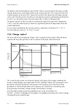
Page 94: ...In case of lead acid batteries the nominal capacity is adjusted by a fixed factor of 1 C For NiCd batteries a factor of 0 75 C is used 13 4 Charge control The Sunny Island uses a three phase charge co...

Page 95: ...ship and the process diagram of the charging phases and charging processes Once this constant voltage phase is finished the Sunny Island switches to float charge which again carries out constant volta...

Page 96: ...and thus compensating the electrolytes The boost charge process can charge the battery up to approx 85 to 90 13 4 2 Full Charge Every 14 days or 8 nominal charge throughputs the Sunny Island initiate...

Page 97: ...charging device If an external charger or charge controller is connected to the battery and the criteria for a full charge are fulfilled due to external charging the Sunny Island treats this as if it...

Page 98: ...where the Sunny Island is predominantly in float charge The silent mode is activated after the time set for float charge 224 02 SilentTmFlo parameter has expired The Sunny Backup system remains in sil...

Page 99: ...efine the start time using the 223 01 BatPro1TmStr parameter and define the stop time using the 223 02 BatPro1TmStp parameter Level 2 The second level of the battery preservation mode ensures that the...

Page 100: ...vation mode can be exited by manually starting the Sunny Island If within 5 minutes see above charging current is detected the Sunny Island continues to operate otherwise it switches off again 13 6 Ba...

Page 101: ...the ohmic resistance of the battery up to the input of the Sunny Island master The default value of the parameter 221 06 BatWirRes is 0 m The resistance is made up of the resistance of cable 1 fuse r...

Page 102: ...rid and generator This generally allows both operating modes to be used without making additional adjustments The parameter settings and display values distinguish between settings or values which are...

Page 103: ...re to connect a larger generator or a higher grid current The maximal current in the system is limited to 150 A 14 1 2 Generator Start Options The Sunny Island supports the following options for start...

Page 104: ...he wiring for a generator that cannot be started remotely The generator is also always switched off manually The Sunny Island then automatically switches to operation without generator GenReq Signal T...

Page 105: ...ing for a generator capable of autostart If the generator is started manually in this operating mode the Sunny Island detects the running generator and connects it once the warm up time has expired If...

Page 106: ...ed the Sunny Island disconnects itself and disables the GnReq signal The following figure shows the principle of starting the generator via the GenMan generator control A manual generator start at the...

Page 107: ...pleted The following process diagrams provide an overview of the start stop behavior of the Sunny Island during manual generator operation NOTICE Occurrence of unpredictable operating states Never car...

Page 108: ...tor 8 Minimum stop time has expired Transfer relay 1 Manual generator start 2 Generator is running detected beginning of warm up phase 3 Warm up phase completed 4 Generator is connected 5 Generator cu...

Page 109: ...r designates the battery charge state at which the generator is started during the t1 time and GnSocTm1Stp designates the charge state at which the generator is switched off during t1 The GnSocTm2Str...

Page 110: ...t charging process see section 13 4 Charge control page 94 is activated before the cutoff limit GnSocTm1Stp or GnSocTm2Stp is reached the generator request is disabled again If a full or equalization...

Page 111: ...erator run time If once this time has expired the average power is below the cutoff limit the generator is stopped again The following process diagrams provide an overview of the start stop behavior o...

Page 112: ...ction 10 Generator power down time expired generator disconnection 11 Stop time has expired 1 Generator start by Sunny Island using GenMan 2 Generator start by GenMan 3 Beginning of GenMan warm up tim...

Page 113: ...alue it is also reduced absorption phase see section 13 4 Charge control page 94 If the 234 15 GnCtlMod parameter is set to CurFrq the generator is also limited at frequencies lower than the nominal f...

Page 114: ...ped If a generator fault e g generator failure is detected the generator is also disconnected and then stopped immediately In doing so the power down time is skipped Once the stop time 234 09 GnStpTmM...

Page 115: ...is fully charged the frequency limits the power output of the AC feed in generators Sunny Boy If the generator is now manually started for example the frequency would be lowered if required as the Su...

Page 116: ...nection is blocked for at least 231 03 ExtLkTm or 234 09 GnStpTmMin Generator Failure If a generator failure is detected failure on the master phase the generator is disconnected immediately and a sto...

Page 117: ...2 Grid The Sunny Island supports the operation of grid backup systems on the grid Here a distinction is made between two main states either a main power grid and stand alone grid are connected or a ma...

Page 118: ...unny Boy perform a charge operation if required 14 2 4 Grid Reconnection In stand alone operation the Sunny Island constantly checks whether the grid has been reconnected see above If for the time int...

Page 119: ...the 224 01 SilentEna parameter set to enable default disable In this case the Sunny Island is set to standby mode if the charge has been completed and the battery has been in float charge for some ti...

Page 120: ...s exceeded for the time 232 10 GdRvTm the grid is disconnected After reverse power connection is blocked for at least 231 03 ExtLkTm Grid Failure If a grid failure is detected failure at the master ph...

Page 121: ...limits the power output of the AC feed in generators PV inverters in the stand alone grid If the grid is now reconnected the frequency would be lowered if required as the Sunny Island is synchronized...

Page 122: ...connection also located on the Sunny Island 2 Connect the positive pole of the DigIn connection to a NO connection of an auxiliary contact of the transfer switch 3 Connect the positive pole of the Bat...

Page 123: ...shedding dependent on an external source Automatic connection disconnection of loads Connection only occurs if the device is connected to an external source e g generator or if the absorption phase is...

Page 124: ...e electrolyte pump MccBatFan Multicluster Battery Fun relay is used for automatic battery room ventilation switching the fan MccAutoLod Multicluster Auto Loadshedding Automatic disconnection of loads...

Page 125: ...ommunication cable connected to the respective master The Multicluster Piggy Back MC PB is mounted at the external communication plug in position in the Sunny Island For orientation refer to the follo...

Page 126: ...ow cable to establish communication between the master of the main cluster and the masters of the extension clusters The gray cable is used for external communication via RS485 needed for the system m...

Page 127: ...e plugs inside the Sunny Island master 3 Plug the RJ45 plug in the lower socket The termination resistor remains plugged in the upper one 4 Lead the RJ45 cable into the next Sunny Island and connect i...

Page 128: ...ltage frequency type 230V_50Hz 220V_60Hz default setting is 230V_50Hz System configuration 3Phase 1Phase 1 1Phase 2 1Phase 3 1Phase 4 MC Box for multicluster operation choose MC Box Default setting 1P...

Page 129: ...hown here 2 Press and hold ENTER on the main cluster master The remaining time is shown on the display as beams A peep is heard The main master is on and operating The green LED is on 16 3 2 Stopping...

Page 130: ...1 of the nominal power per 1 difference in charge status Thus when initial charge states differ equalization of the charge states over the course of time is ensured If all batteries in the various clu...

Page 131: ...cluster operation automatic frequency adjustment AFRA can only be activated at the main master By default it is set to Enable 16 8 Firmware Update Carry out the update on all masters of the individual...

Page 132: ...ension cluster is operating If a slave device in the extension cluster fails this does not cause the master device to stop The devices in an extension cluster are only started up if the respective dev...

Page 133: ...ing the rotary switch only within the first 10 operational hours Setting via Sunny Boy Control Sunny WebBox Setting via Sunny Data Control You can only carry out the setting via the rotary switch on t...

Page 134: ...manual of the PV inverter Stand alone grid operation and the desired language are set 17 1 3 Settings Via Communication or Sowftare You can set the PV inverter to stand alone grid operation OFF Grid v...

Page 135: ...hold to 65 2 Set the parameter FrqCtl Max or Frequency monitoring upper maximum threshold to 65 3 Set the parameter FrqCtl lLim or Frequency monitoring upper minimum threshold to 55 4 Set the paramete...

Page 136: ...ft damp cloth Never use solvents abrasives or corrosive materials for cleaning Take care not to accidentally press the membrane buttons during cleaning Only clean the membrane keypad when the Sunny Is...

Page 137: ...rters cluster in kVAr Number Name Description displayed value Description 01 InvOpStt Operating mode of the Sunny Island Standby Standby Run Operation EmCharge Emergency charging operation Error Error...

Page 138: ...ng operation Error Error Startup Transfer standby operation 02 InvPwrAtSlv1 Effective power of the Sunny Island slave 1 in kW 03 InvVtgSlv1 Voltage of the Sunny Island slave 1 in V 04 InvCurSlv1 Curre...

Page 139: ...ng operation Error Error Startup Transfer standby operation 02 InvPwrAtSlv2 Effective power of the Sunny Island slave 2 in kW 03 InvVtgSlv2 Voltage of the Sunny Island slave 2 in V 04 InvCurSlv2 Curre...

Page 140: ...ng operation Error Error Startup Transfer standby operation 02 InvPwrAtSlv3 Effective power of the Sunny Island slave 3 in kW 03 InvVtgSlv3 Voltage of the Sunny Island slave 3 in V 04 InvCurSlv3 Curre...

Page 141: ...in hh mm ss 05 BatChrgOp Active charging process Boost Boost charge Full Full charge Float Float charge Equalize Equalization charge Silent Silent Mode 06 TotBatCur Total battery current of the cluste...

Page 142: ...ive power of the external source in kW 02 TotExtCur Total current of the external source in A 03 TotExtPwrRt Total reactive power in kVAr 04 TotLodPwr Total averaged active power of the consumers clus...

Page 143: ...Run1h Requested for 1 hour Start Manual ExtSrcReq Requested via an external source 02 GnStt Generator state Off Off Init Init Ready Waiting for request ready Warm Warming up Connect Connecting Run Op...

Page 144: ...gSlv1 Voltage of the external source slave 1 in V 03 ExtCurSlv1 Current of the external source slave 1 in A 04 ExtPwrRtSlv1 Reactive power of the external source slave 1 in kVAr Number Name Descriptio...

Page 145: ...unny Island Chargers in kWh 02 TotSicTyEgyCntIn Total daily yield of all Sunny Island Chargers in kWh 03 TotSicPvPwr Total PV power of all Sunny Island Chargers in W 04 TotSicBatCur Total battery curr...

Page 146: ...f the third Sunny Island Charger in kWh 03 Sic3PvPwr PV power of the third Sunny Island Charger in W 04 Sic3PvVtg PV voltage of the third Sunny Island Charger in V 05 Sic3BatVtg Battery voltage of the...

Page 147: ...1 Inverter Settings 210 Number Name Description Value Description Default value 01 InvVtgNom Nominal voltage of the Sunny Island 230 V 230 V 50 Hz 230 V 220 V 220 V 60 Hz 02 InvChrgCurMax Maximum AC...

Page 148: ...electrolyte in gel or AGM Absorbent Glass Mat Separator VRLA FLA A sealed lead acid battery with liquid electrolyte NiCd Nickel cadmium battery 02 BatCpyNom Nominal battery capacity E C10 U C20 100 A...

Page 149: ...1 h 48 h 10 h 05 CycTmFul 1 h 180 h 14 h 06 CycTmEqu Equalization charge cycle time 7 days 365 days 180 days 07 ChrgVtgBoost Nominal value of cell voltage for normal charge VRLA 2 4 V FLA 2 55 V NiCd...

Page 150: ...0 hh mm ss 04 BatPro2TmStp End time of battery preservation mode level 2 09 00 00 hh mm ss 05 BatPro1Soc Battery charge state for battery preservation mode level 1 0 70 20 06 BatPro2Soc Battery charge...

Page 151: ...al battery current sensor type 60 mV type A 60 mV 100 A 03 BatCurGain50 External battery current sensor type 50 mV type A 50 mV 100 A 04 BatCurAutoCal Automatic calibration of the external battery cur...

Page 152: ...gMin Minimum grid voltage 230 V 50 Hz 184 V 220 V 60 Hz 194 V 02 GdVtgMax Maximum grid voltage 230 V 50 Hz 264 5 V 220 V 60 Hz 242 V 03 GdCurNom Gird nominal voltage 16 A 04 GdFrqNom Grid nominal freq...

Page 153: ...allation country The installation land is set based on the corresponding applicable norm The defaut value is set according to your order GER_VDE01 26_1_1 Germany AS4777 USA Other others 41 FedInMod Fe...

Page 154: ...Name Description displayed value Description Default value 01 GdSocTm1Str SOC limit for switching on the grid for time 1 40 02 GdSocTm1Stp SOC limit for switching off the grid for time 1 80 03 GdSocT...

Page 155: ...tor nominal frequency at nominal load 230 V 50 Hz 50 Hz 220 V 60 Hz 60 Hz 05 GnFrqMin Minimum generator frequency 230 V 50 Hz 44 64 Hz 220 V 60 Hz 50 Hz 06 GnFrqMax Maximum generator frequency 230 V 5...

Page 156: ...nRvPwr Generator reverse power active power 100 W 14 GnRvTm Permissible time for reverse power reverse current 30 sec 15 GnCtlMod Generator regulation Cur Current Cur CurFrq Frequency 20 GdAlSns AI se...

Page 157: ...f generator for time 2 80 07 GnTm1Str Time 1 for generator request in hh mm ss Begin Time 1 End Time 2 08 GnTm2Str Time 2 for generator request in hh mm ss Begin Time 2 End Time 1 09 GnPwrEna Generato...

Page 158: ...tion charge Both Full and Equalization charge 19 GnStrDigIn Generator start upon signal of activated digital input Disable Enable Disable Enable Disable Number Name Description Value Description Defau...

Page 159: ...HP plant for time 2 80 05 ChpTm1Str Time 1 for CHP plant request in hh mm ss Begin Time 1 End Time 2 06 ChpTm2Str Time 2 for CHP plant request in hh mm ss Begin Time 2 End Time 1 07 ChpPwrEna Activate...

Page 160: ...oLod1Soc SOC1 Loadshedding AutoLod2Soc SOC2 Loadshedding Tmr1 Timer 1 Tmr2 Timer 2 AptPhs Absorption phase GnRn Generator in operation ExtVfOk External source voltage and frequency OK GdOn Grid in ope...

Page 161: ...Generator in operation ExtVfOk External source voltage and frequency OK GdOn Grid in operation connected Error Error Warn Warning Run Operation BatFan Battery ventilation room AcdCir Acid circulation...

Page 162: ...or load shedding 1 stop for t2 50 05 Lod1Tm1Str Time 1 in hh mm ss for loadshed 1 Begin Time 1 End Time 2 06 Lod1Tm2Str Time 2 in hh mm ss for loadshed 1 Begin Time 2 End Time 1 07 Lod2SocTm1Str SOC l...

Page 163: ...relay control timer 1 03 RlyTmr1Dur Run time in hh mm ss for relay control timer 1 hh mm ss 04 RlyTmr1Cyc Repetition cycle time for timer 1 Single One time Single Dayly daily Weekly weekly 05 RlyTmr2S...

Page 164: ...SOC1 Loadshedding AutoLod2Soc SOC2 Loadshedding Tmr1 Timer 1 Tmr2 Timer 2 AptPhs Absorption phase GnRn Generator in operation ExtVfOk External source voltage and frequency OK GdOn Grid in operation c...

Page 165: ...r2 Timer 2 AptPhs Absorption phase GnRn Generator in operation ExtVfOk External source voltage and frequency OK GdOn Grid in operation connected Error Error Warn Warning Run Operation BatFan Battery v...

Page 166: ...SOC1 Loadshedding AutoLod2Soc SOC2 Loadshedding Tmr1 Timer 1 Tmr2 Timer 2 AptPhs Absorption phase GnRn Generator in operation ExtVfOk External source voltage and frequency OK GdOn Grid in operation c...

Page 167: ...r2 Timer 2 AptPhs Absorption phase GnRn Generator in operation ExtVfOk External source voltage and frequency OK GdOn Grid in operation connected Error Error Warn Warning Run Operation BatFan Battery v...

Page 168: ...SOC1 Loadshedding AutoLod2Soc SOC2 Loadshedding Tmr1 Timer 1 Tmr2 Timer 2 AptPhs Absorption phase GnRn Generator in operation ExtVfOk External source voltage and frequency OK GdOn Grid in operation c...

Page 169: ...r2 Timer 2 AptPhs Absorption phase GnRn Generator in operation ExtVfOk External source voltage and frequency OK GdOn Grid in operation connected Error Error Warn Warning Run Operation BatFan Battery v...

Page 170: ...uration slave1 cluster slave 1 1Phase1 slave2 cluster slave 2 slave3 cluster slave 3 1Phase1 1 phase 1 Sunny Island 1Phase2 1 phase 2 Sunny Islands 1Phase3 1 phase 3 Sunny Islands 3Phase 3 phase 3 Sun...

Page 171: ...9 Multicluster Box 9 3 MC Box 12 Multicluster Box 12 3 24 ClstMod Cluster type in multicluster operation Single Cluster MainCluster ExtensionClst 1 ExtensionClst 2 ExtensionClst 3 25 ClstAdr Cluster a...

Page 172: ...ring run time in hours Number Name Description Value Description Default value 01 Adr Device address Master Address Master slave1 Address slave2 Address slave3 Address 02 FwVer Firmware version of the...

Page 173: ...space available BadFileSys No filing system recognized Incomp Incompatible filing system Parameters Parameter set write access ParamFailed Parameter set write access failed WriteLogData Log data write...

Page 174: ...Sunny Island slave 1 03 OnTmhSlv1 Operating hours of the Sunny Island slave 1 in hours 04 PhSlv1 Phase of the Sunny Island slave 1 L1 Phase L1 L2 Phase L2 L3 Phase L3 05 OpSttSlv1 Operating mode of t...

Page 175: ...rial number of the Sunny Island slave 2 03 OnTmhSlv2 Operating hours of the Sunny Island slave 2 n hours 04 PhSlv2 L1 Phase L1 L2 Phase L2 L3 Phase L3 05 OpSttSlv2 Operating mode of the Sunny Island s...

Page 176: ...f the Sunny Island slave 3 03 OnTmhSlv3 Operating hours of the Sunny Island slave 3 in hours 04 PhSlv3 Phase of the Sunny Island slave 3 L1 Phase L1 L2 Phase L2 L3 Phase L3 05 OpSttSlv3 Operating mode...

Page 177: ...g ampere hours 07 AhCntOut Meter for battery discharging ampere hours 08 BatTmpPkMin Minimum battery temperature in C 09 BatTmpPkMax Maximal batter temperature in C 10 EquChrgCnt Equalization charge m...

Page 178: ...4 SocHgm060 Frequency distribution of the charge state in percent 60 SOC 50 25 SocHgm050 Frequency distribution of the charge state in percent 50 SOC 40 26 SocHgm040 Frequency distribution of the char...

Page 179: ...Ah V 36 OcvMax Maximal open circuit voltage 2 12 V Number Name Description 01 GdEgyCntIn Energy meter for grid feed in in kWh 02 GdEgyCntOut Energy meter for power taken from the grid in kWh 03 GdEgyT...

Page 180: ...e Description Value Description Default value 01 InvRs Triggering a new start of the Sunny Island Restart Restart 02 InvRmOpEna Time controlled inverter operation Disable Enable Disable Enable Disable...

Page 181: ...Sunny Island Charger 2 Sic3 Sunny Island Charger 3 Sic4 Sunny Island Charger 4 SicAll all Sunny Island Chargers 08 TstClstCom Activates the communication test between the individual clusters Off off T...

Page 182: ...ion displayed value Description Default value 01 ChrgSelMan Manual Equalization Charge Idle Wait Idle Start Start Stop stop Number Name Description Value Description Default value 01 GnManStr Manual g...

Page 183: ...e Description Default value 01 ParaSto Save parameter settings Set1 Parameter Set1 Set2 Parameter Set2 02 ParaLod Load parameter settings Set1 Parameter Set1 Set2 Parameter Set2 Factory Load factory s...

Page 184: ...ror or fault the Sunny Island goes into standby Proceed as follows to confirm an error 1 Remove the cause 2 Confirm error with ENTER 3 Start the Sunny Island again 20 2 Autostart Handling The Sunny Is...

Page 185: ...l active on slave 1 the ENTER symbol is displayed at the end of the line After confirming the fault on the master using ENTER the fault is forwarded to the corresponding slave The master shows the fol...

Page 186: ...egory INV Meaning of the abbreviations F marks an error W marks a warning and E marks an event In the event of an error and provided it is recorded is displayed for an error that has occurred and C is...

Page 187: ...tion mode level 1 E222 Battery preservation mode level 2 E223 Battery preservation mode level 3 Display no Description E401 Automatic generator start due to set criteria battery charge state power tim...

Page 188: ...E613 Transfer relay on slave 2 open E614 Transfer relay on slave 2 closed E615 Transfer relay on slave 3 open E616 Transfer relay on slave 3 closed E617 Relay 2 open E618 Relay 2 closed E619 Relay 2...

Page 189: ...changed E707 New system configured in QCG E708 part 1 of the firmware updated E709 part 2 of the firmware updated E710 cluster firmware updated E711 MMC SD card inserted E712 Parameters from MMC SD c...

Page 190: ...2 Failure 1 Malfunction Failure that can only be detected during operation Device switches off Device can be restarted immediately autostart 3 Failure 2 Malfunction Failure that can also be detected...

Page 191: ...ent limit short circuit control active for too long on slave 1 W119 1 AC current limit short circuit control active for too long on slave 2 W120 1 AC current limit short circuit control active for too...

Page 192: ...W311 1 Relay protection on slave 2 W312 1 Relay protection on slave 3 W314 1 external voltage failure W315 1 grid generator disconnection due to insufficient external voltage W316 1 grid generator dis...

Page 193: ...tage limits on slave 2 W338 1 grid generator disconnection due to breached voltage limits on slave 3 W339 1 grid generator disconnection due to voltage rise protection W340 1 grid generator disconnect...

Page 194: ...prohibited quick grid disconnection W502 1 grid reverse current prohibited quick grid disconnection on slave 1 W503 1 grid reverse current prohibited quick grid disconnection on slave 2 W504 1 grid re...

Page 195: ...ange of battery voltage exceeded on slave 2 W719 1 measuring range of battery voltage exceeded on slave 3 F720 4 short circuit or cable break on transformer temperature sensor F721 4 short circuit or...

Page 196: ...erature sensor slave 3 F753 1 Invalid system time W754 2 Communication with Multicluster Box interrupted W755 1 Battery Preservation Mode 1 W756 1 Battery Preservation Mode 2 W757 1 Battery Preservati...

Page 197: ...on with Sunny Island Charger 2 for more than 24 h W871 1 Pole of battery connection is reversed or short circuit on the Sunny Island Charger 3 W872 1 Battery overvoltage Sunny Island Charger 3 W873 1...

Page 198: ...C and SOH page 93 To restart the Sunny Island see section 9 5 Reactivating the Device Following Automatic Shutdown page 63 The external battery fuse may have been triggered Why is it not possible to c...

Page 199: ...nings and Failures page 79 Check the card on your PC laptop and use a new SD card if necessary Why does my Sunny Island stay on even though I switched the DC circuit breaker to Off Your Sunny Island m...

Page 200: ...combinations of voltage and frequency limits The possible ranges for voltage and frequency of the Sunny Island allow the combination of special frequencies and voltages that result in transformer satu...

Page 201: ...onfiguration Guide QCG page 55 Follow the instructions up to point 2 The emergency charge mode is described below 1 Choose Emerg Charge in QCG with ENTER 2 Confirm the following view with ENTER 3 Set...

Page 202: ...ing SMA Solar Technology AG 202 SI5048 TEN093630 Technical Description 5 Use the down arrow key The notification shown here is issued 6 Press ENTER to confirm 7 Press ENTER The emergency charging oper...

Page 203: ...lues are shown in the display Parameters cannot be changed during the charging process If the device is restarted the settings that were saved before the ECM are loaded Premature ending of the emergen...

Page 204: ...nput ports 2 x Battery and 4 x Sunny Island Chargers 1 X auxiliary voltage output with 8 A BATFUSE B 03 Load shedding contactor 3 pole load shedding contactor with a 48 V coil for Sunny Island The loa...

Page 205: ...al AC current IAC nom 21 A Maximal current peak value for 60 ms IAC max 120 A Harmonic distortion of output voltage KVAC 3 Power factor cos 1 1 Input data Input voltage adjustable UAC ext 230 V 172 5...

Page 206: ...n with no load in standby mode 25 W 4 W General data Dimensions W x H x D in mm 467 x 612 x 235 Weight in kg ca 63 EC Declaration of Conformity Enclosed download area www SMA de en Protection rating a...

Page 207: ...Number of buttons 4 Display 2 line display Multi function relays 2 Communication RS485 galvanically isolated optional Memory card SD card Digital input level Dig In high level starting at 9 V up to 63...

Page 208: ...y Island Firmware version of the Sunny Island Fault indication Type of battery connected Nominal battery capacity Nominal battery voltage Communication products connected Type and size of additional e...

Page 209: ......

Page 210: ......

Page 211: ...he product under incorrect safety or protection conditions Altering the product or supplied software without authority The product malfunctions due to operating attached or neighboring devices beyond...

Page 212: ...4 4PMBS 5FDIOPMPHZ XXX 4 EF...

Reviews: