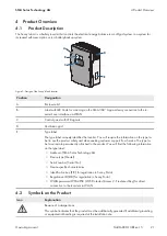
4 Product Overview
SMA Solar Technology AG
Operating manual
SI44M-80H-13-BE-en-15
26
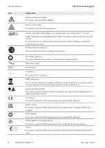
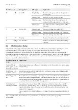
Position
Icon
Designation
LED signal
Explanation
E
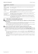
Grid LED
Not glowing
There is no voltage present from the generator or
the utility grid.
Glowing green
Generator or utility grid is connected.
Glowing orange
The Sunny Island is synchronizing the stand-
alone grid with the generator or the utility grid.
Glowing red
Error at the connection of the generator or the
utility grid.
F
Battery LED
Glowing green
The state of charge is more than 50%.
Glowing orange
The state of charge is between 50% and 20%.
Glowing red
The state of charge is less than 20%.
G
Standby
−
Position of the buttons for switching on and off
H
AC operation
−
Position of the button for starting and stopping
operation
4.6
Multifunction Relay
Using 2 multifunction relays, each Sunny Island can control various functions and can display operating states and
warning messages. Within a cluster, the master can also access the multifunction relays of the slaves.
In a single-cluster system with battery-backup function, the multifunction relays of the master are set permanently. In
multicluster systems with Multicluster-Box 12 (MC-BOX-12.3-20), multifunction relays 1 and 2 in the master of the main
cluster and multifunction relay 2 in slave 1 of the main cluster are set permanently. Furthermore, free multifunctional
relays can be used for additional functions.
Possible function or
output
Explanation
Control of the tie
switch and of the con-
tactors for grounding
In the battery-backup system, the multifunction relays control the contactors for grid coupling
and grounding.
Switch cycles in the
multicluster system
In multicluster systems with Multicluster-Box 12, multifunction relays control different switch
cycles in the multicluster system.
Controlling genera-
tors
The multifunction relay activates if a generator request is received from the Sunny Island in-
verter's generator management system. With the multifunction relay, you can control genera-
tors with an electrical remote-start function or connect a signal generator for generators with
no autostart function (see Section 6.5.10, page 46).
Controlling load-
shedding contactors
Depending on the state of charge of the battery, the multifunction relay picks up and thus
controls up to 2 load-shedding contactors. Basically, you can install a one-stage or a two-
stage load-shedding scheme. Note the restrictions that depend on the selected system (see
Section 6.5.12, page 48).
You can adjust the thresholds for the state of charge of the battery depending on the time of
day.
Time control for exter-
nal processes
The multifunction relays can be time-controlled (see Section 6.5.13, page 50).

