6 Electrical Connection
SMA Solar Technology AG
Operating manual
SI44M-80H-13-BE-en-15
40
2.
WARNING
Danger to life from electric shock due to incorrect insulation
In the case of faulty insulation, supposedly de-energized parts or cables may be live. Touching live components
or cables can result in death or serious injury due to electric shock.
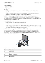
• When making the following connections, always insert a silicone tube (see Section 6.6.5, page 60).
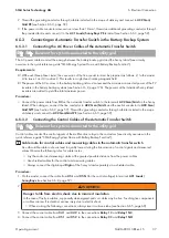
3. On the master of the main cluster, connect the control cable of
X113 1
and
X113 2
to the
Relay2 C
and
Relay2 NO
4. On the main cluster's master, connect the control cable of
X112 1
and
X112 2
to the
Relay1 C
and
Relay1
NC
terminals when a Grid-Connect-Box is installed in addition to the Multicluster-Box 12.
6.5.5.3
Connecting the Measuring Cable of the Multicluster-Box 12
Requirements:
☐ The inverters to be connected must be Sunny Island 6.0H / 8.0H inverters.
☐ The utility grid must be connected to the multicluster system (see Multicluster-Box 12 operating manual).
Procedure:
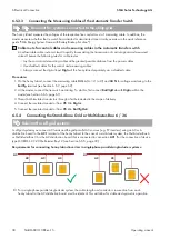
1. On every Sunny Island of the main cluster, connect the measuring cable for voltage monitoring of the Multicluster-
Box 12 to
ExtVtg
. First connect the wires of
X112 3
and
X112 4
at the master to
ExtVtg
2. Connect the conductors of
X112 3
and
X112 4
on the master to
ExtVtg
on each Sunny Island of the main
cluster.
3. Connect the conductors of
X112 7
and
X112 8
on Slave 1 to
ExtVtg
on each Sunny Island of the main cluster.
4. Connect the conductors of
X112 9
and
X112 10
on Slave 2 to
ExtVtg
on each Sunny Island of the main cluster.
☑ The measuring cable for voltage monitoring from the Multicluster Box 12 is connected.
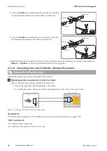
5. At the master of the Main Cluster, connect the AC contactor monitoring. To do this, first connect
BatVtgOut-
with
DigIn-
within the master(see Section 6.6.6, page 61).
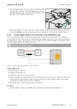
6. Thread both insulated conductors through a ferrite included in the scope of delivery.
7. Connect the insulated conductor from
X113 3
to
Ba
.
8. Connect the insulated conductor from
X113 4
to
DigIn+
.
☑ The monitoring of the grid contactor is connected.
6.5.6
Connecting the Generator in an Off-Grid System
Relevant for off-grid systems
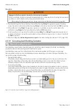
For a single system and single-cluster system, connect the generator to the
AC2
terminal of the Sunny Island. For a
multicluster system, connect the generator directly to the Multicluster-Box (see the Multicluster-Box documentation).
WARNING
Danger to life from electric shock due to incorrect connection of the neutral conductor
Connecting the neutral conductor incorrectly can cause failure of the protective functions in the system. This can
result in death or serious injury.
• Connect the neutral conductor to the
AC2
or
AC1
terminal.

