7 Commissioning
SMA Solar Technology AG
Operating manual
91
SI44M-80H-13-BE-en-15
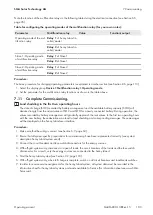
7. Ensure that the multifunction relay used for controlling the first stage of load shedding is set to
1-stage load
shedding or 1st stage with 2-stage load shedding
(see Section 7.10.2, page 102).
8. Ensure that the multifunction relay used for controlling the second stage of load shedding is set to
1st stage with
2-stage load shedding
.
Set the SOC threshold for the additional time period
1. Select
Device > Load shedding 1
.
2. Set the parameter
Limit battery state of charge for start load shedding 1 in add time range
to the lower
SOC threshold for the first stage of load shedding.
3. Set the parameter
Limit battery state of charge for stop load shedding 1 in add time range
to the upper
SOC threshold for the first stage of load shedding.
4. Select
Device > Load shedding 2
.
5. Set the parameter
Limit battery state of charge for start load shedding 2 in add time range
to the lower
SOC threshold for the second stage of load shedding.
6. Set the parameter
Limit battery state of charge for stop load shedding 2 in add time range
to the upper
SOC threshold for the second stage of load shedding.
7. Ensure that the multifunction relay used for controlling the first stage of load shedding is set to
1-stage load
shedding or 1st stage with 2-stage load shedding
(see Section 7.10.2, page 102).
8. Ensure that the multifunction relay used for controlling the second stage of load shedding is set to
1st stage with
2-stage load shedding
.
7.7.6
Setting Utilization of Excess Energy in Off-Grid Systems
Relevant for off-grid systems
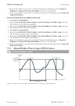
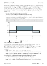
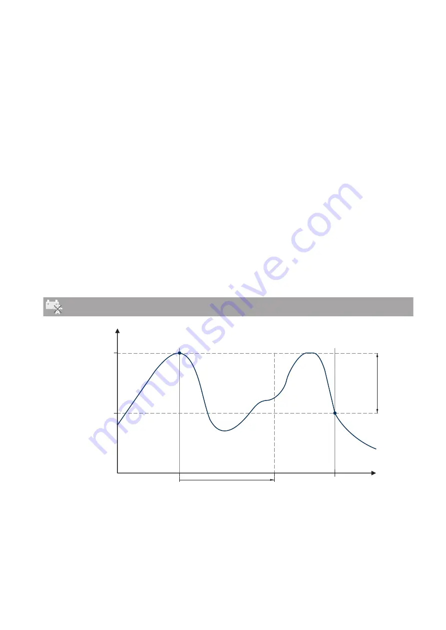
Time
Minimum time
Cell voltage
Voltage dif
fer
ence
Time of deactivation
Time of activation
Target value
of the cell voltage
in the constant
voltage phase
Figure 22: Switching-on time and switching-off time for utilization of excess energy during constant voltage phase

