6 Electrical Connection
SMA Solar Technology AG
Operating manual
33
SI44M-80H-13-BE-en-15
6.2
Overview of the Connection Area
NO C
NC
Relay 1
NO C
NC
Relay 2
A
B
E
F
I
K
L
N
Q
R
C
M
D
G
P
H
O
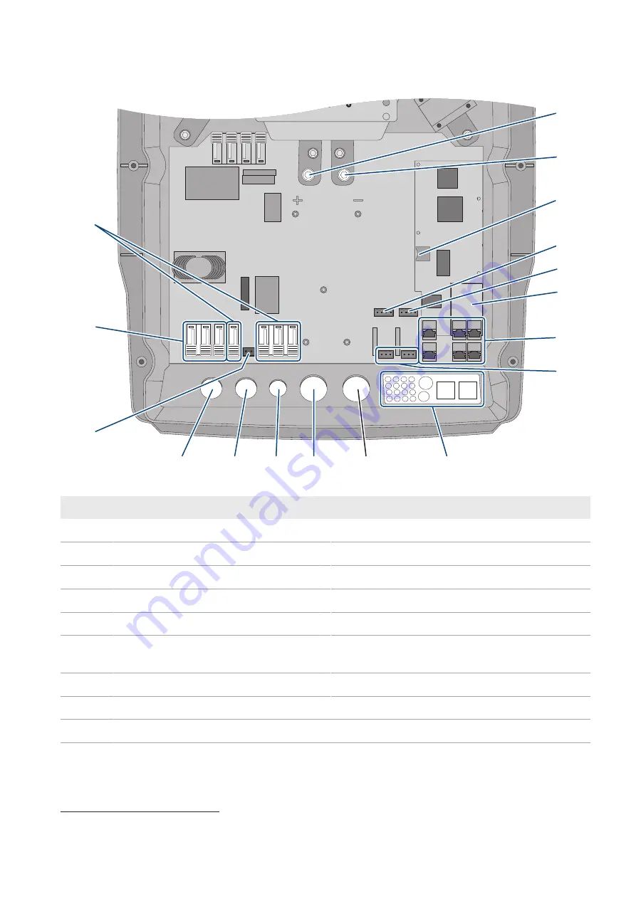
Figure 7: Connection area of the Sunny Island inverter
Position
Designation
Position
Designation
A
DC+
connection
K
Enclosure opening for
DC-
B
DC-
connection
L
Enclosure opening for
DC+
C
Slot for optional micro SD card
M
Enclosure opening
ExtVtg
D
BatTmp
and
BatCur
connections
N
Enclosure opening
AC2
E
BatVtgOut
and
DigIn
connections
O
Enclosure opening
AC1
F
Slot for optional communication interface SI-
SYSCAN.BGx
4)
P
ExtVtg
connection
G
Connecting the communication unit
Q
AC1
connection
H
Relay1
and
Relay2
connections
R
AC2
connection
I
Cable feed-through plate
4)
If the inverter was ordered with the Communication for multicluster system order option, SI‑SYSCAN.BGx is installed in each master.


