6 Electrical Connection
SMA Solar Technology AG
Operating manual
SI44M-80H-13-BE-en-15
50
Procedure:
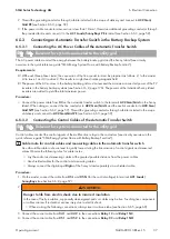
1. Ensure that the load-shedding contactor only disconnects loads from the system. This ensures that the battery can
be recharged from AC sources in the system.
2.
Observe default setting of the battery inverter
The default setting of the battery inverter uses the multifunction relay
Relay2
for load shedding.
• Before connecting the load shedding device, check whether the multifunction relay
Relay2
is available.
3. If the multifunction relay
Relay2
is available, connect the multifunction relay
Relay2
for load shedding
4. If the multifunction relay
Relay2
is not available, connect the multifunction relay
Relay1
for load shedding
5. Write down the terminal assignment of the load shedding terminal for setting the multifunction relays. Tip: Use the
table provided in this document (see Section 7.10.2, page 102).
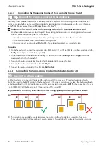
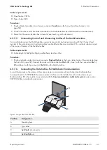
Connecting the multifunction relay Relay2 for load shedding
1. Connect the insulated conductor for coil connection
A1
of the load-shedding contactor on the Sunny Island to
terminal
Relay2 NO
2. Connect the insulated conductor for coil connection
A2
to terminal
BatVtgOut−
3. Connect terminal
Bat
to terminal
Relay2 C
. Use the same conductor cross-section as that of the cable
for the load-shedding contactor.
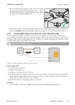
Connecting the multifunction relay Relay1 for load shedding
1. Connect the insulated conductor for coil connection
A1
of the load-shedding contactor on the Sunny Island to
terminal
Relay1 NO
2. Connect the insulated conductor for coil connection
A2
to terminal
BatVtgOut−
3. Connect terminal
Bat
to terminal
Relay1 C
. Use the same conductor cross-section as that of the cable
for the load-shedding contactor.
6.5.13 Connecting the Time Control for External Processes
The Sunny Island has two timers for time-dependent control of external processes. For each timer, you can set the
starting day and time that the multifunction relay is to be switched once, daily or weekly.
Requirements:
☐ The technical requirements of the multifunction relay must be met (see Section 16, page 175).
Cable requirements:
☐ Conductor type: copper wire
☐ Conductor cross-section: 0.2 mm² to 2.5 mm²
Procedure:
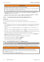
1.
WARNING
Danger to life from electric shock due to incorrect insulation
In the case of faulty insulation, supposedly de-energized parts or cables may be live. Touching live components
or cables can result in death or serious injury due to electric shock.
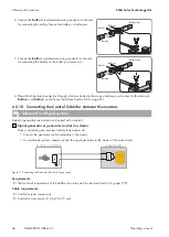
• When making the following connections, always insert a silicone tube (see Section 6.6.5, page 60).
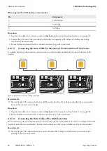
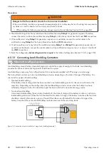
2. Connect the control cable on the Sunny Island to either multifunction relay
Relay1
or
Relay2
. Use the
C
and
NO
connections.
3. During configuration, enter the value
TM1
for timer 1 or the value
TM2
for timer 2 in the table of settings (see


