6 Electrical Connection
SMA Solar Technology AG
Operating manual
59
SI44M-80H-13-BE-en-15
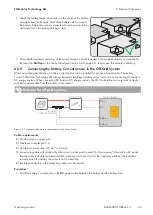
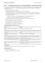
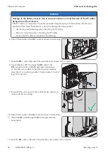
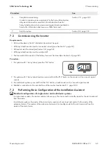
7. Insert the line conductor as far as it will go into terminal
L
and push the lever down.
8. Connect the grounding conductor (see Section 6.6.3, page 59).
9. Ensure that the seal insert is positioned correctly in the cable gland.
10. Tighten the swivel nut of the cable gland (torque: 4 Nm).
6.6.3
Connecting the Grounding Conductor
The Sunny Island must be connected via a grounding conductor on the terminal
AC1
or
AC2
to the ground potential.
The conductor cross-section of the grounding conductor must be 10 mm² or larger. If the conductor cross-section is
smaller, an additional grounding conductor must connect the Sunny Island with the ground potential.
Cable requirements:
☐ Cross-section of the connected line conductor or (maximum 16 mm²)
☐ Cable diameters: 7 mm to 14 mm
Procedure:
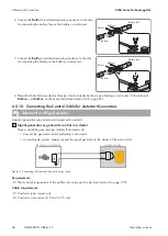
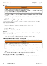
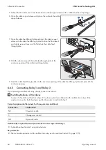
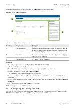
1. Push the lever of terminal
AC1 Loads/SunnyBoys PE
or
AC2 Gen/Grid PE
upward.
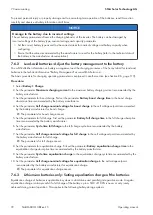
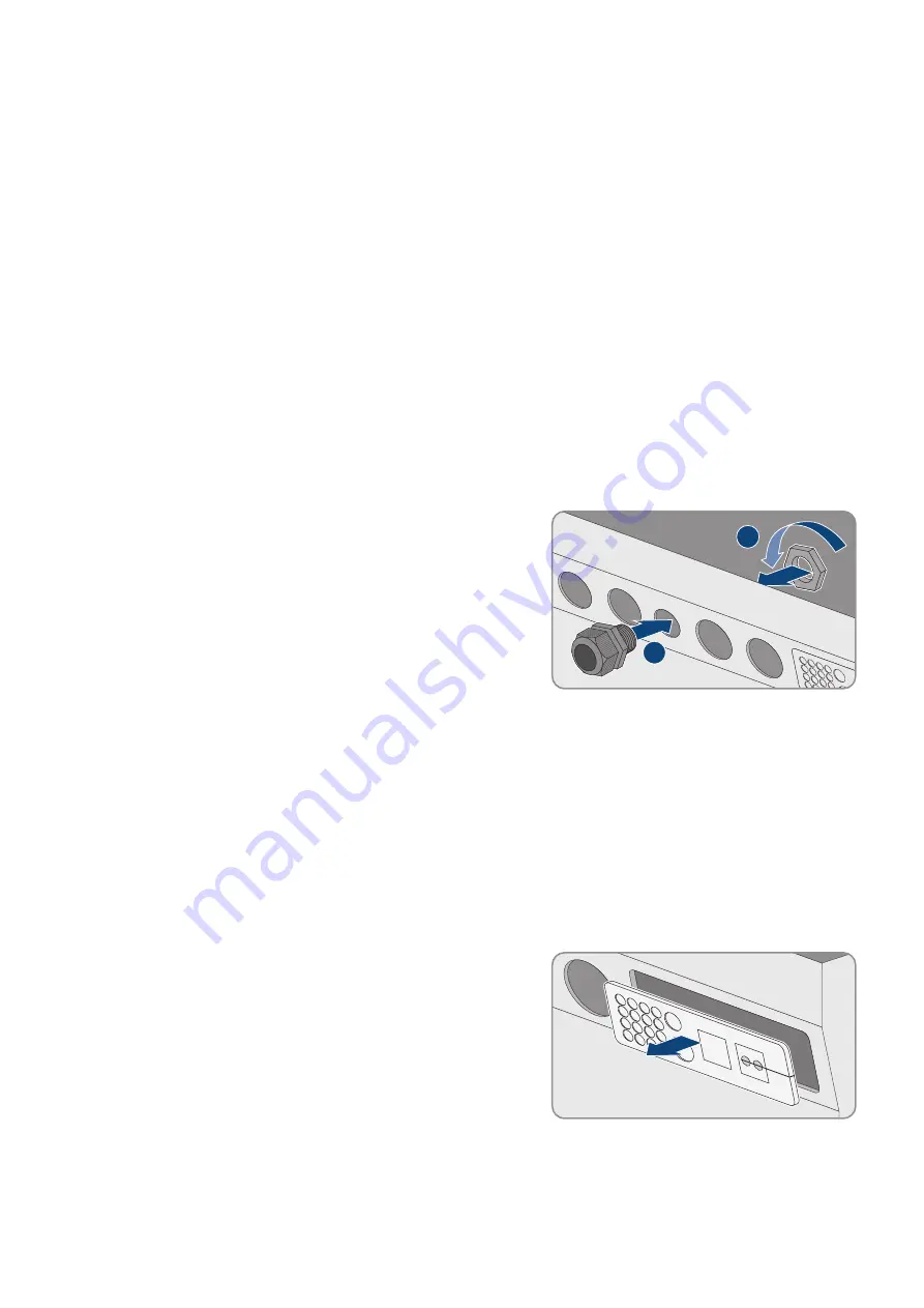
2. Attach the M25 cable gland to the
AC1
or
AC2
enclosure
opening using the counter nut (torque: 7 Nm).
2
1
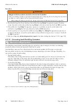
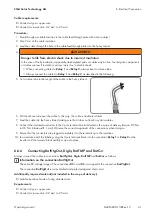
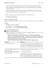
3. Strip off 13 mm of the insulation of the grounding conductor.
4. Lead the cable through the cable gland into the Sunny Island.
5. Thread the grounding conductor through a ferrite included in the scope of delivery.
6. Insert the grounding conductor as far as it will go into terminal
AC1 Loads/SunnyBoys PE
or
AC2 Gen/
Grid PE
and move the lever downward.
7. Tighten the swivel nut of the cable gland (torque: 2.6 Nm).
6.6.4
Connecting the Data Cable
Always proceed as follows to connect data cables.
Procedure:
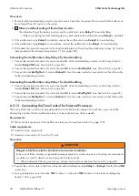
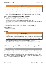
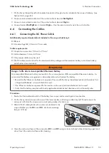
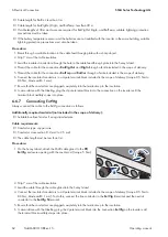
1. Push the cable feed-through plate out of the enclosure from
outside.
2. Retain the cable feed-through plate for later use.
3. Lead the data cable through the enclosure opening.
4. Connect the data cable.

