6 Electrical Connection
SMA Solar Technology AG
Operating manual
SI44M-80H-13-BE-en-15
62
☐ Cable length for BatCur: less than 3 m
☐ Cable length for BatVtgOut, DigIn, and BatTemp: less than 30 m
☐ If cable lengths of 30 m and more are required for BatVtgOut, DigIn, and BatTemp, suitable lightning protection
precautions must be taken.
☐ If the battery temperature sensor and the batteries are not installed with the inverter in the same building, suitable
lightning protection precautions must also be taken.
Procedure:
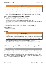
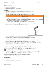
1. Break through a suitable location in the cable feed-through plate with a sharp object.
2. Strip 7 mm of the cable insulation.
3. Lead the insulated conductors through the hole in the cable feed-through plate into the Sunny Island.
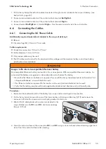
4. Thread the cable for the connections
BatVtgOut
and
DigIn
through a ferrite included in the scope of delivery.
5. Thread the cable for the connections
BatTmp
and
BatCur
through a ferrite included in the scope of delivery.
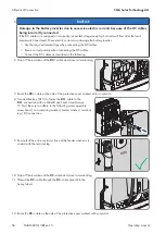
6. Connect the insulated conductors to a 4-pole terminal block included in the scope of delivery (torque: 0.5 Nm to
0.6 Nm, blade width: 1 mm):
7. Ensure that the conductors are plugged completely into the terminals up to the insulation.
8. In accordance with the labeling, plug the 4-pole terminal block into the connection on the inverter until the
terminal block audibly snaps into place.
6.6.7
Connecting ExtVtg
Always connect the cable to the ExtVtg connection as follows.
Additionally required material (not included in the scope of delivery):
☐ Suitable bootlace ferrules if using stranded wire
Cable requirements:
☐ Conductor type: copper wire
☐ Conductor cross-section: 0.2 mm² to 2.5 mm²
☐ The cable length must be less than 3 m.
Procedure:
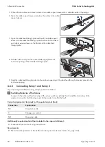
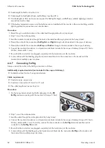
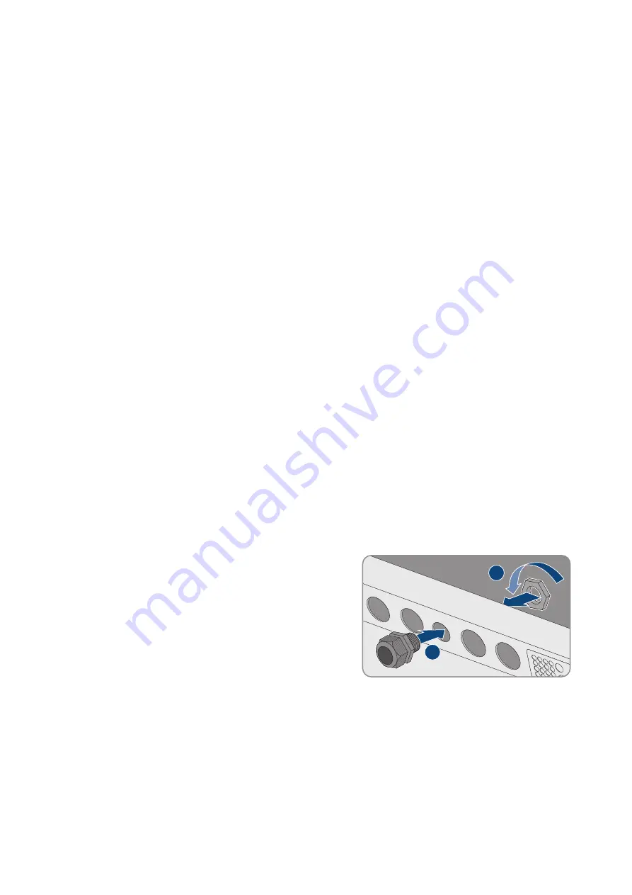
1. On the Sunny Island, attach the M20 cable gland to the
PE/
ExtVtg
enclosure opening with the counter nut (torque: 5 Nm).
2
1
2. Strip 7 mm of the cable insulation.
3. Lead the cable through the cable gland into the Sunny Island.
4. Connect the insulated conductors to a 2-pole terminal block included in the scope of delivery (torque: 0.5 Nm to
0.6 Nm, blade width: 1 mm). To do this, connect the line conductor to the
ExtVtg L
terminal and the neutral
conductor to the
ExtVtg N
terminal.
5. Ensure that the conductors are plugged completely into the terminals up to the insulation.
6. In accordance with the labelling, plug the 2-pole terminal block into the connection
ExtVtg
on the inverter until
the terminal block audibly snaps into place.

