6 Electrical Connection
SMA Solar Technology AG
Operating manual
SI44M-80H-13-BE-en-15
66
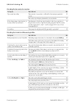
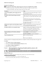
Checking the Wiring of the Communication Products
Test point
Test criterion
Ok
Electricity supply to communication
products
The plug-in power supply units are plugged in.
☐
The communication products are connected to an electricity supply.
☐
Termination of the communication
buses
The communication buses are connected to the first and last device in
the bus.
☐
Multicluster-Box control and measur-
ing cable (
BackupVtgCur
)
The cable length must be less than 30 m.
☐
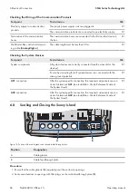
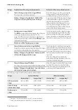
Checking the System Devices
Test point
Test criterion
Ok
System components
All system devices are correctly connected (see the manuals for the
devices).
☐
Ensure by measuring that all system devices are connected with the
same ground potential.
☐
AC1
connection
After the system-specific connection, the required components are con-
nected at terminal
AC1
(see Installation - Quick Reference Guide of
the System Used).
☐
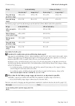
AC2
connection
After the system-specific connection, the required components are con-
nected at terminal
AC2
(see Installation - Quick Reference Guide of
the System Used).
☐
6.8
Sealing and Closing the Sunny Island
NO C
NC
Relay 1
NO C
NC
Relay 2
A
B
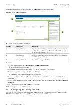
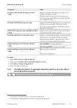
Figure 15: Position of the cable glands and the cable feed-through plate.
Position
Designation
A
Cable glands
B
Cable feed-through plate
Procedure:
1. Ensure that the cable glands (A) completely seal the enclosure openings.
2. Seal unused enclosure openings with filler plugs on the cable feed-through plate (B).

