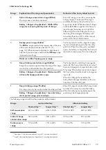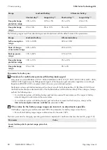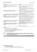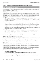
7 Commissioning
SMA Solar Technology AG
Operating manual
85
SI44M-80H-13-BE-en-15
7.6.7
Energy-saving mode
The battery inverter has an energy-saving mode where the power consumption is less than 7 watts. When entering and
leaving the energy-saving mode, the battery inverter behaves depending on the operating mode (stand-alone mode
and parallel grid operation mode).
Energy-saving mode during stand-alone mode
In stand-alone mode, the energy-saving mode is coupled to the 3-level battery protection mode (see Section 7.6.6,
page 84). The power saving mode occurs under the following conditions:
• The SOC limiting value of level 1 in battery protection mode has been undershot and charging current has flowed
into the battery within 5 minutes.
• The SOC limiting value of level 2 in battery protection mode has been undershot and no charging current has
flowed into the battery within 5 minutes.
.
Energy-saving mode during parallel grid operation mode
In parallel grid operation mode, the energy-saving mode is coupled to the battery utilization ranges for self-
consumption systems. The power saving mode occurs under the following conditions:
• In the case of self-consumption systems without a battery-backup grid, this occurs when there is no surplus PV
energy available to charge the battery in the state-of-charge conservation range
PVRes
• For self-consumption systems with battery-backup grid, the energy-saving mode activates when no surplus PV
energy is available to charge the battery in the state-of-charge conservation range
PVRes
or when the deep
discharge protection range
BatRes
is reached (see Section 7.6.4.3, page 77).
7.6.8
Configuring the Resistance of the Battery Cable
You can optimize the battery management if you set the resistance of the battery cable in expert mode.
SUNNY ISLAND
BATTERY
Cable 1
Cable 2
Length l
1
Length l
2
BATTERY FUSE
Figure 20: Designation of the cable
The resistance of the battery cable is the sum of the resistance of cable 1, the battery fuse and the resistance of cable
2.
Resistance of a single cable:
R
Cu
= ρ x l/A
• ρ = specific resistance for copper (ρ = 0.018
Ω mm²⁄m
)
• l = total length of the conductor (outward con return conductor = twice the cable length) in m
• A = conductor cross-section in mm²
resistance of total battery cable:
R
BatRes
= R
cable 1
+ R
battery fuse
+ R
cable 2
• R
BatRes
= total resistance of the battery cable
• R
Cable 1
= Calculated resistance of cable 1
• R
Cable 2
= Calculated resistance of cable 2


