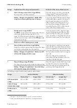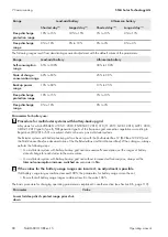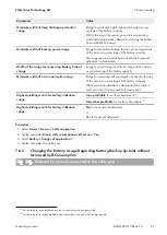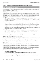
7 Commissioning
SMA Solar Technology AG
Operating manual
SI44M-80H-13-BE-en-15
86
• R
battery fuse
= total resistance of the battery fuse (see manufacturer documentation)
The basic procedure for changing operating parameters is explained in another section (see Section 8.6, page 113).
Procedure:
1. Calculate the individual cable resistances.
2. Calculate the total resistance of the battery cable.
3. Select
Battery > Battery
.
4. Select the parameter
Line resistance of battery connection
and set this to the resistance of the battery cable.
7.6.9
Setting the Control of the Battery Room Fan
The basic procedure for changing operating parameters is explained in another section (see Section 8.6, page 113).
Procedure:
1. Select
Device > Multifunction relay
.
2. Set the parameter
Temp lmt for multifunct. relay with batt comp fan
to the battery temperature at which the
fan is to be switched on.
3. Ensure that the multifunction relay used for control is set to
Battery compartment fan
or
Battery fan in
Multicluster
(see Section 7.10.2, page 102).
4. Ensure that the battery room is sufficiently ventilated in the case of malfunctions – for example, on failure of the
multifunction relay.
7.7
Energy management
7.7.1
Setting Load Shedding in a Multicluster System
The basic procedure for changing operating parameters is explained in another section (see Section 8.6, page 113).
Relevant for off-grid systems
The load contactor in the Multicluster-Box is a load-shedding contactor and is controlled depending on the state of
charge of the batteries.
Significance of the SOC thresholds:
When the state of charge of a battery reaches the lower SOC threshold, the load contactor is opened. The state of
charge of the battery of the main cluster and the states of charge of the batteries of the extension clusters are
evaluated. The load contactor disconnects the loads from the stand-alone grid. When the state of charge of all
batteries reaches the upper SOC threshold during recharging, the load contactor closes. The load-shedding contactor
connects the loads to the stand-alone grid.
Procedure:
1. Select
Device > Load shedding 1
.
2. Set the parameter
Limit of battery state of charge for start
to the lower SOC threshold.
3. Set the parameter
Limit of battery state of charge for stop
to the upper SOC threshold. The upper SOC
threshold must be at least 10 percentage points above the lower SOC threshold.
4. Select
Device > Load shedding 1 > Additional time range >
.
5. Set the parameter
Time load shedding 1
and the parameter
Start time additional time range load
shedding 1
each to the same value, e.g. to
00:00:00
. This will switch the time-dependent load shedding off.
6. If the off-grid system is a multicluster system, ensure that the parameter of the multifunction relay is set to
Load
shedding in Multicluster

