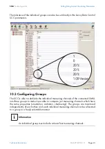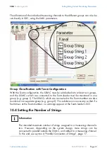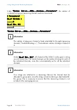
SMA
Technologie AG
Connection
Technical Description
SSM-TEN072310
Page 31
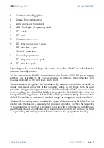
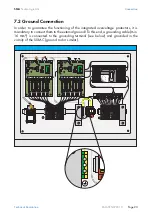
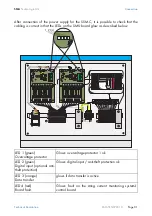
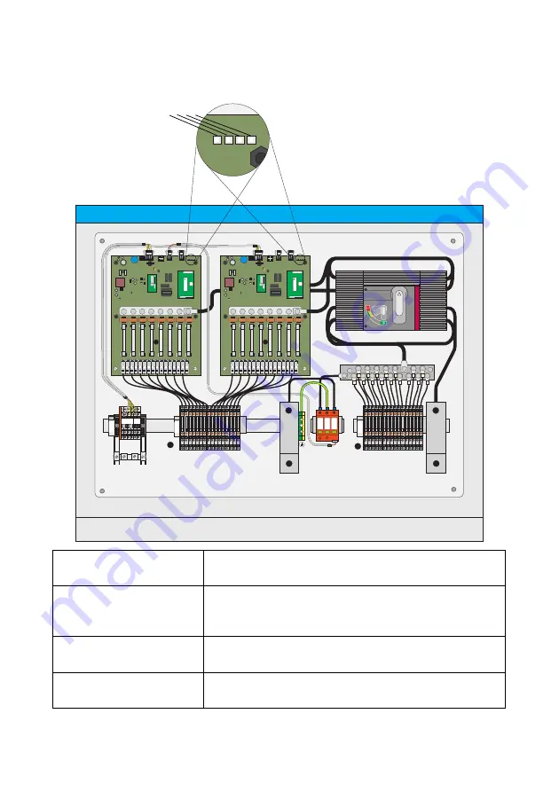
After connection of the power supply for the SSM-C, it is possible to check that the
cabling is correct in that the LEDs on the SMU board glow as described below.
LED 1 (green)
Overvoltage protector
Glows: overvoltage protector 1 ok
LED 2 (green)
Digital input (optional anti-
theft protection)
Glows: digital input / anti-theft protection ok
LED 3 (orange)
Data transfer
glows if data transfer is active
LED 4 (red)
Board fault
Glows: fault on the string current monitoring system's
control board
1 2 3 4 5 6
Z9-X9
L+
L+
Z2-X2
1
2
3
4
5
6
7
8
9
10
11
12
13
14
15
16
L-
L-
L-
1 1 2 2 3 3 4 4 5 5
6 6
7 7 8 8
L+
12
1 1 2 2 3 3 4 4 5 5
6 6
7 7 8 8
L-
12
Z1-X1
1
2
3
4
5
6
7
8
9
10
11
12
13
14
15
16
L+
FA
2064706
0002374
Vers.:
A1
485HCVBP
-0
1
11
31
11/07
FA
2064676
0068725
Vers.:C2
2903 06/07
Vers.:A1
S/N
1728
SMU8HV
-DVPB
Ms60-
DC8FS
FA
2064706
0002374
Vers.:
A1
485HCVBP
-0
1
1131
11
/0
7
FA
2064676
0068725
Vers.:C2
2903 06/07
Vers.:A1
S/N
1728
SMU8HV
-DVPB
Ms60-
DC8FS
1 2 3 4

