SMA
Technologie AG
Connection
Technical Description
SSM-TEN072310
Page 25
7.4.3 Data Line Connection in the SSM-C
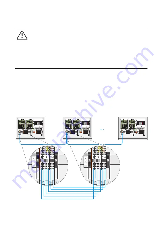
Connection of the data line occurs at the connection terminals in the SSM-C. To this end,
a suitable screwdriver with a 5.5 x 0.8 mm blade must be used so as not to damage
the terminals. To ensure a secure connection between the data line and the spring-type
terminal, 12 mm of insulation must be stripped from the data line before it is fed into the
connection terminals. Not stripping the required length can lead to a poor connection
that may damage the SSM-C.
The wiring between the individual SSM-Cs is realized in a bus, upon observation of the
terminal assignments.
WARNING!
All SSM-Cs in the string must be disconnected via the load-disconnecting
switches and the isolation terminals before connecting the data line.
If there is no circuit breaker in the SSM-C, the DC fuses in the SC must be pulled
in order to avoid reverse voltage from the inverter.
Only after this has taken place may cabling work be carried out on the SSM-C.
1 2 3 4 5 6
Z9-X9
L+
L+
Z2-X2
1
2
3
4
5
6
7
8
9
10
11
12
13
14
15
16
L-
L-
L-
1 1 2 2 3 3 4 4 5 5
6 6
7 7 8 8
L+
1
2
1 1 2 2 3 3 4 4 5 5
6 6
7 7 8 8
L-
1
2
Z1-X1
1
2
3
4
5
6
7
8
9
10
11
12
13
14
15
16
L+
1 2 3 4 5 6
Z9-X9
L+
L+
Z2-X2
1
2
3
4
5
6
7
8
9
10
11
12
13
14
15
16
L-
L-
L-
1 1 2 2 3 3 4 4 5 5
6 6
7 7 8 8
L+
1
2
1 1 2 2 3 3 4 4 5 5
6 6
7 7 8 8
L-
1
2
Z1-X1
1
2
3
4
5
6
7
8
9
10
11
12
13
14
15
16
L+
1 2 3 4 5 6
Z9-X9
L+
L+
Z2-X2
1
2
3
4
5
6
7
8
9
10
11
12
13
14
15
16
L-
L-
L-
1 1 2 2 3 3 4 4 5 5
6 6
7 7 8 8
L+
1
2
1 1 2 2 3 3 4 4 5 5
6 6
7 7 8 8
L-
1
2
Z1-X1
1
2
3
4
5
6
7
8
9
10
11
12
13
14
15
16
L+

