Connection
SMA
Technologie AG
Page 28
SSM-TEN072310
Technical Description
Termination with Team Configuration
In a Team configuration, the termination resistor must be removed from the RJ45 socket
"485 Out" at the SMU8 hub power supply unit in the SC, and replaced by the provided
CAT5 cable. The cabling for a Team configuration is shown in the figure below.
7.4.5 Connection in the Sunny Central
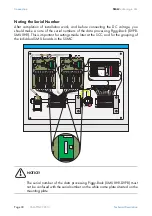
Connection of the data line in the SC occurs at the X4 plug of the SMU8 hub power
supply unit. This power supply unit provides the +55 V DC supply voltage, and the
connection of the RS485 bus for the SSM-C.
The maximum number of SSM-Cs which can be connected to an SMU8 hub power
supply unit is limited to 5.
In each case, the cabling from the power supply unit is realized in a bus (see RS485
and supply voltage wiring plan on the following page). For each SSM-C (except for
the last SSM-C), the two RS485 data lines and the four power supply lines are to be
connected in the connection area, in observation of the terminal assignments in the
SSM-C.
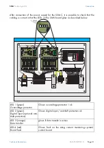
String M
onitor
Powe
r Supp
ly Unit /
Hub
FUSE
L
L
N
N
NC
PE
PE
AC
+55V
SSM
Power
SCC
Data-
Data+
GND
GND
+55V
+55V
SSM
RS485
OUT
RS485
IN
U1-A6
www.SM
A.de
String M
onitor
Powe
r Supp
ly Unit /
Hub
FUSE
L
L
N
N
NC
PE
PE
AC
+55V
SSM
Powe
r
SCC
Data-
Data+
GND
GND
+55V
+55V
SSM
RS485
OUT
RS485
IN
U1-A6
www
.SMA.de
Sunny
Central
Central
Sunny
Contr
ol
ENTER
ESC
Sunny
Central
Central
Sunny
Contr
ol
ENTER
ESC

