background image

SMA


Technologie AG

Configuration of the Sunny Central 

Technical Description

SSM-TEN072310

Page 35

Checking the Detection

The serial numbers found must match the actual serial numbers on the SMU8HV-DVPB
(see figure below).

8.3.3 Setting the Device Address

For identification of the individual SMU boards in the SSM-C, the device address "

SSM

Identifier

" must be set. The "

SSM Identifier

" is not the network address which

is automatically assigned upon detection.
Every SMU board in the SSM-C must be allocated a unique identifier between 1 and
40. This is necessary so that upon occurrence of a fault, the SMU board in the SSM-C
can be located precisely, and analysis can occur in the SCC. This makes
troubleshooting easier, for example, in the event of a string failure, or a deviating string.

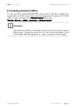
Information

If no "

SSM  Identifier

“ is set, it is not possible for the SCC to determine

which of the SSM-C's SMU boards has the PV array fault.

NOTICE!

The maximum "

SSM Identifier

“ number which can be managed from the

SCC is limited to 40. If "

SSM Identifier

“ is set > 40, analysis thereof is not

possible in the SCC.

Summary of Contents for SSM-C

Page 1: ...Sunny String Monitor Cabinet SSM C Installation and use of the SSM C Technical Description Version 1 0 SSMC TEN072310 98 4000210...

Page 2: ......

Page 3: ...al 7 3 4 Checking the Delivery 8 3 5 Storage 8 3 6 Installation 8 3 7 Special Hazards of Photovoltaic Systems 8 3 8 Special Hazards of Grounded PV Systems 9 3 9 Cabling 10 3 10 Electrical Connection 1...

Page 4: ...Sunny Central 28 8 Configuration of the Sunny Central 32 8 1 Sunny Data Control 32 8 2 Serial Interface Settings 32 8 3 Detection of SSM Cs 33 8 3 1 Registration 33 8 3 2 Detection 33 8 3 3 Setting th...

Page 5: ...eft Protection 51 11 Values of the String Current Monitoring System 53 11 1 Groups Mean Values 53 11 2 Measured Values of the Measuring Channels 54 12 Warnings 55 12 1 Active Warnings 55 12 2 Warnings...

Page 6: ...ing with the aid of the Sunny Data Control software and the data logger Sunny Central Control 1 3 Explanation of the Symbols Used In this document the following terms and symbols are used to describe...

Page 7: ...or the optimal installation and operation of your product Storage of handbooks This operating manual the installation guide the data sheets the operating manuals of installed components and the wiring...

Page 8: ...e or the cabling to be isolated from the entire PV array If a string fuse is triggered this is detected by the software and a warning is generated in the Sunny Central Control SCC which is situated wi...

Page 9: ...uitable for grounded systems Suitable for 1000 V DC Night operation possible for anti theft protection Star shaped RS485 wiring with a maximum individual length of 1000 m Better troubleshooting and co...

Page 10: ...y for any and all damage resulting from inappropriate use of the equipment Appropriate use of the equipment also entails the following Observation of the safety instructions listed here and in the fol...

Page 11: ...nected to the internal strain relief clamp in the base in order to prevent exertion of mechanical strain on the housing Interference testing occurred as per DIN EN 61000 accordingly the installation l...

Page 12: ...dent on the level of solar radiation which means that if a short circuit occurs in the system the existing circuit breakers are not guaranteed to switch off A highly branched generator array may be di...

Page 13: ...e string fuses and connection of the isolation terminals causes the DC voltage of the connected strings to become available in the device The string fuses may only be inserted when the following condi...

Page 14: ...ed out on the SMU board which for example involves unplugging the plug connectors or removing the string fuses is strictly only permissible under voltage free conditions WARNING If the isolation termi...

Page 15: ...the use of DC circuit breakers optionally available for isolating the inverter or the SSM C Even in the case of faults or fire this allows system components to be isolated safely Information Work on t...

Page 16: ...ork on the SSM C may only be performed when the device is safely disconnected from the PV voltage when the device is secured against accidental restarting and when the device has been checked to be vo...

Page 17: ...nsiderably higher than the normal maximum current short circuit of the string Thus the string fuses protect the faulty string The largest permissible string fuse depends on the module type and must be...

Page 18: ...e Double ground fault in a module and or the cabling Despite the fact that these faults are very unlikely and extremely rare in practice preventative measures must still be taken After all these types...

Page 19: ...es a schematic overview of the various components and connection points inside the Sunny String Monitor Cabinet with the cover removed 1 2 3 4 5 6 Z9 X9 L L Z2 X2 1 2 3 4 5 6 7 8 9 10 11 12 13 14 15 1...

Page 20: ...VPB realizes the management of string currents and the SMU board s parameter settings For connection of the DC main lines to the inverter two bolt clamps are integrated within the SSM C The load disco...

Page 21: ...must be routed into the housing s interior in a sealed manner in order to ensure protection rating IP54 Thus it is also imperative to couple the connection cables to the integrated strain relief clamp...

Page 22: ...mm and the rest with so called base filler or coarse gravel grain size 4 8 mm Information When installing the SSM C observe the installation guide which is provided in the base 1 2 3 4 5 6 Z9 X9 L L Z...

Page 23: ...panel remains visible The first front panel should be freely accessible as it must be possible to remove this for any retrofitting work or in the event of failure 1 2 3 4 5 6 Z9 X9 L L Z2 X2 1 2 3 4...

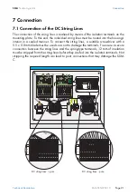
Page 24: ...ust be stripped from the string lines before they are fed into the isolation terminals Not stripping the required length can lead to poor connections that may damage the SSM C 1 2 3 4 5 6 Z9 X9 L L Z2...

Page 25: ...with a nut and appropriated cable lug NOTICE See that the terminal screws are tightened 1 2 3 4 5 6 Z9 X9 L L Z2 X2 1 2 3 4 5 6 7 8 9 10 11 12 13 14 15 16 L L L 1 1 2 2 3 3 4 4 5 5 6 6 7 7 8 8 L 1 2 1...

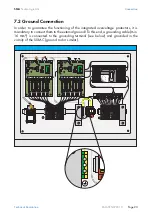
Page 26: ...and grounded in the vicinity of the SSM C ground rod or similar 1 2 3 4 5 6 Z9 X9 Z2 X2 1 2 3 4 5 6 7 8 9 10 11 12 13 14 15 16 L 1 1 2 2 3 3 4 4 5 5 6 6 7 7 8 8 L 1 2 1 1 2 2 3 3 4 4 5 5 6 6 7 7 8 8...

Page 27: ...d in parallel in each case in order to guarantee a cable cross section of 1 mm For communication however only two conductors are required data and data The remaining two wires are used as reserves 7 4...

Page 28: ...st be disconnected via the load disconnecting switches and the isolation terminals before connecting the data line If there is no circuit breaker in the SSM C the DC fuses in the SC must be pulled in...

Page 29: ...wer Supply Unit Hub FUSE L L N N NC PE PE AC 55V SSM Power SCC Data Data GND GND 55V 55V SSM RS485 OUT RS485 IN U1 A6 www SMA de Sunny Central Central Sunny Contro l ENTER ESC String Monit or Power Su...

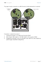
Page 30: ...e last SSM C 2 Removing the other jumpers on the SMU boards in the respective SSM C 3 Plugging the termination resistor into the RJ45 socket 485 Out at the SMU8 hub power supply unit default configura...

Page 31: ...number of SSM Cs which can be connected to an SMU8 hub power supply unit is limited to 5 In each case the cabling from the power supply unit is realized in a bus see RS485 and supply voltage wiring pl...

Page 32: ...E AC 55V SSM Power SCC Data Data GND GND 55V 55V SSM RS485 OUT RS485 IN U1 A6 www SMA de 1 2 3 4 5 6 Z9 X9 L L Z2 X2 1 2 3 4 5 6 7 8 9 10 11 12 13 14 15 16 L L L 1 1 2 2 3 3 4 4 5 5 6 6 7 7 8 8 L 1 2...

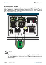
Page 33: ...mber of the data processing Piggy Back SMU8HV DVPB must not be confused with the serial number on the white name plate situated on the mounting plate 1 2 3 4 5 6 Z9 X9 L L Z2 X2 1 2 3 4 5 6 7 8 9 10 1...

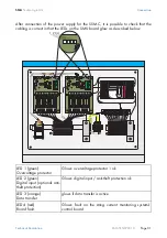
Page 34: ...3 orange Data transfer glows if data transfer is active LED 4 red Board fault Glows fault on the string current monitoring system s control board 1 2 3 4 5 6 Z9 X9 L L Z2 X2 1 2 3 4 5 6 7 8 9 10 11 1...

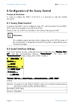
Page 35: ...rial Interface Settings The COM1 interface must be configured at the SCC Select the menu Device Set up and the corresponding submenu Interfaces The menu item Communication allows editing of the COM1 i...

Page 36: ...be accepted and saved Under the menu item Registration check whether all serial numbers of the data processing Piggy Backs SMU8HV DVPB from the respective SSM Cs SMU boards are registered correctly Ea...

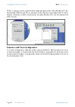
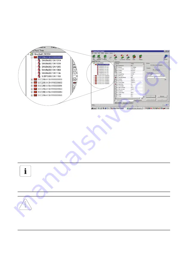
Page 37: ...s to be visible in SDC s online display Detection via SDC only functions correctly after the SCC has first detected all SMU boards Detection with Team Configuration In a Team configuration detection o...

Page 38: ...on detection Every SMU board in the SSM C must be allocated a unique identifier between 1 and 40 This is necessary so that upon occurrence of a fault the SMU board in the SSM C can be located precisel...

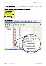
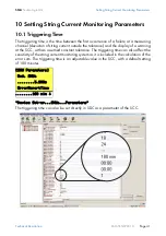
Page 39: ...ng is adjusted in the SSC s Parameters menu for the respective detected serial number Device Set up SMUs Devices Parameters SSM Identifier can also be set directly in SDC s SMU parameters This allows...

Page 40: ...egistered for each SMU board This is done by changing the ID number to 99 The ID number can be changed via the Registration menu item Device Set up SMUs Devices Registration Information Select the ser...

Page 41: ...the SC s nominal AC power and if the average string current of the individual groups is greater than or equal to 0 5 A 9 2 Polling Interval The mean values of the measuring channels of each SMU board...

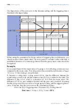
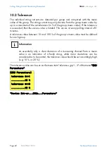
Page 42: ...f e g 10 i e 5 5 A totaling is not performed If however a string shows a string current of 6 A then the difference between the actual string current 6 A and the tolerance limit 5 5 A is added to the t...

Page 43: ...ifference in the above example is 4 5 A which equates to a deviation of 90 from the mean value If the settings in the above example remain the same i e tolerance at 10 and triggering time at 10 minute...

Page 44: ...t outside the tolerance and the display of a warning at the SCC with an assumed constant tolerance The triggering time can also affect the sensitivity of the string current monitoring system as it is...

Page 45: ...xcess value is totaled This occurs at every polling interval of 5 minutes A tolerance value between 10 and 100 of the group s mean value must be defined for each group The tolerance value can be set v...

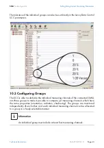
Page 46: ...CC is able to subdivide the individual measuring channels of the connected SMUs into three groups to make it possible to compare just measuring channels which have the same properties orientation radi...

Page 47: ...measuring channel of an SMU can be allocated to a group in a freely selectable manner Under Group all chan all measuring channels of the SMU are allocated to one group This avoids having to allocate...

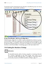
Page 48: ...to the Team leader must be monitored in one group e g group 1 The SSM Cs which are connected to the Team member are also monitored in a separate group e g group 2 This subdivision is necessary so that...

Page 49: ...channels The default setting is 1 The maximum number of strings is limited to 4 Information Under No of Str All all channels of the SSM C can be given a string count of one to four This avoids having...

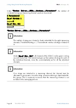
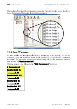
Page 50: ...5 Time Windows In order to filter out temporary effects e g shadowing in the morning etc on an individual string it is possible to define a time window for every individual channel of the SSM C For e...

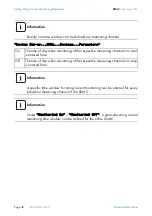
Page 51: ...n monitoring of the respective measuring channel is to start is entered here Off The time of day when monitoring of the respective measuring channel is to stop is entered here Information A specific t...

Page 52: ...tring Current Monitoring Parameters Technical Description SSM TEN072310 Page 49 The time windows of the individual strings for each measuring channel can also be set directly in Sunny Data Control by...

Page 53: ...the overnight shutdown the SSM C continues to be supplied with power during the night This provides the option of activation and analysis of the anti theft protection see section 10 7 Setting the Ant...

Page 54: ...ion of activating the anti theft protection To this end alarm contact 2 on the SMU8HV must be incorporated into the monitoring circuit The contacts at the solar modules are to be implemented as NC con...

Page 55: ...f the signal chain an anti theft warning appears in the SCC display and an e mail message is sent immediately Under Device Set up SMUs Parameters the anti theft protection can be activated and deactiv...

Page 56: ...SCC activate the submenu SMUs from the menu Device Set up In the Measured Values submenu the mean values of the measuring channels are displayed for each group and updated at 5 minute intervals Devic...

Page 57: ...Set up SMUs Devices Measured Values Under this menu path the currents of the individual measuring channels of the connected SMUs are displayed and updated at 5 minute intervals Device Set up SMUs Devi...

Page 58: ...automatically reset at midnight Like the warnings the individual error sums of the measuring channels are also reset at this time 12 1 Active Warnings Warnings present at the SSM C are displayed here...

Page 59: ...LEDs on the SMU board in the SSM C Danger to life For work to be carried out within the SSM C this device must be disconnected see safety instructions in section 3 13 1 2 3 4 5 6 Z9 X9 L L Z2 X2 1 2 3...

Page 60: ...s are not mounted in the individual SSM Cs Is the bridge 7 9 fitted on the side of the SCC Is COM1 at the SCC equipped with an RS485 Piggy Back Is COM1 configured correctly in the SCC LED 1 green Over...

Page 61: ...M C The latest version of the design tool for calculation of cable lengths Also the latest version of Sunny Data Control for download Address SMA Technologie AG Hannoversche Strasse 1 5 34266 Niesteta...

Page 62: ...ction conditions Altering the product or supplied software without authority The product malfunctions due to operating attached or neighboring devices beyond statutory limit values In case of unforese...

Page 63: ......

Page 64: ...A Technologie AG Hannoversche Strasse 1 5 34266 Niestetal Germany Tel 49 561 9522 4000 Fax 49 561 9522 4040 E Mail Info SMA de Freecall 800 SUNNYBOY Freecall 800 78669269 Innovation in Systems Technol...

Reviews: