String Current Monitoring Function
SMA
Technologie AG
Page 38
SSM-TEN072310
Technical Description
9 String Current Monitoring Function
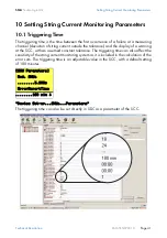
The string currents are continually recorded by the respective data processing Piggy-
Back (SMU8HV-DVPB) on the SMU board in the SSM-C, and averaged over a time
period of 30 seconds. A mean value for each measuring channel is transferred to the
SSC at 5 minute intervals. In the SSC, a mean value is calculated for all queried
measuring channels which belong to a group. If a measuring channel deviates from the
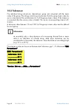
mean value of the group by more than the (adjustable) tolerance setting, this deviation
is added to a sum at 5 minute intervals. If the sum of the deviations exceeds the
internally calculated error sum, then a warning is displayed.
The mean values of the measuring channels and groups can be recorded at the SSC
for documentation or information purposes.
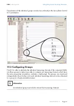
9.1 Activation of String Current Monitoring
If power levels or string currents are very low, monitoring is impractical. Thus, string
current monitoring only becomes active if the DC power exceeds 5 % of the SC's
nominal AC power, and if the average string current of the individual groups is greater
than or equal to 0.5 A.
9.2 Polling Interval
The mean values of the measuring channels of each SMU board in the SSM-C are
cyclically transferred to the SSC every 5 minutes. When setting parameters in the SSC,
it can therefore happen that the function of newly set parameters is first applied after
about 5 minutes. The communication between the SSM-Cs and the SSC is kept to an
absolute minimum to avoid interference in the communication occurring on the bus
between Team leader and Team member.
9.3 Error Sum
The SSM-C is able to distinguish between temporary fluctuations in solar radiation and
real faults, and only indicates faults that have actually occurred (e.g. total failure of a
string).
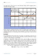
The deviations of each measuring channel that are higher than the set tolerance are
totaled, measuring channel by measuring channel, at a polling interval of 5 minutes,
and error sums are created for every individual measuring channel. The error sum is
calculated based on the set tolerance value and the triggering time.
Calculation of the error sum:
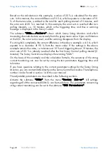
An example will be used to illustrate the measuring process and the error sum
calculations in more detail.
Error sum (%) = Triggering time (min) x Tolerance (%) / 5 min


