background image

1  Definition of Active Power, Reactive Power and Apparent Power

SMA Solar Technology AG

2

IPC_STP-TI-en-14

Technical Information

This document provides basic information on reactive power and how to set the inverter in order to feed reactive power 

into the utility grid in compliance with standards and demand.

1  Definition of Active Power, Reactive Power and Apparent Power

Electrical power is the product of current and voltage. While current and voltage have stable values with direct current, 

the strength and the direction of both current flow and voltage change regularly in alternating current. In the utility grid, 

current and voltage have a sinusoidal shape, so that their product, electrical power, is also sinusoidal. In DC systems, the 

sign of the power indicates the direction in which the electrical energy, in the form of active power, is transported.  

In general, this also applies in an AC circuit. However, the power may not always be positive or negative, but rather its 

sign can fluctuate periodically, causing the power to oscillate back and forth. This oscillating power does not do any work 

and is therefore referred to as reactive power. The time delay between the current and voltage curve -- its so-called phase 

shift -- is a value which is easy to measure and characteristic of the relation between active power and reactive power at 

the point under consideration in the electric circuit.

1.1  Active Power P

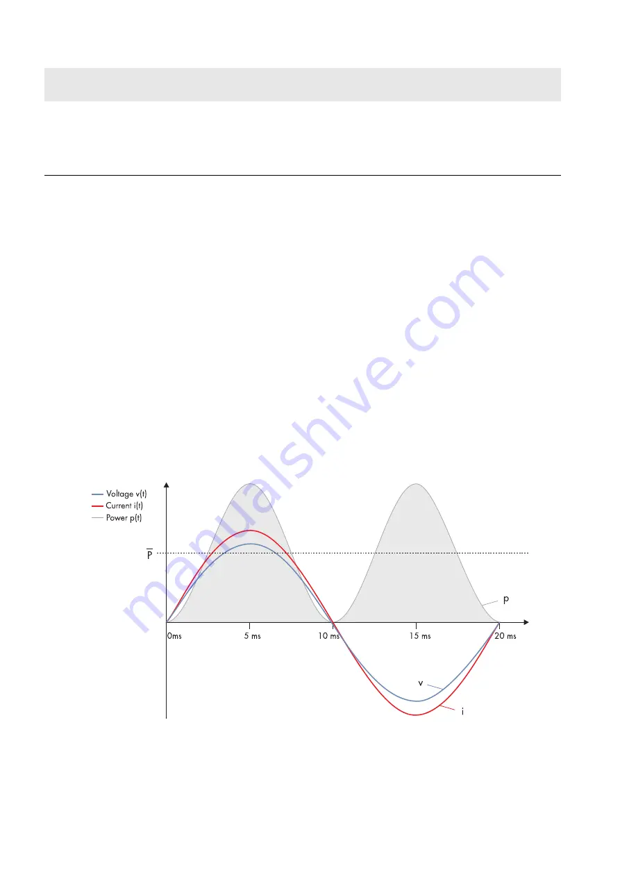
With no phase shift between progression of current i(t) and voltage v(t) over time, both always have the same sign and 

simultaneously reach their maximum and minimum values. The power oscillates between zero and the positive maximum 

value. Averaged over time, this results in a positive power value P (unit: W; Watt) and only active power is generated P. 

This behavior occurs only when ohmic loads are the only loads in the electric circuit. In a real utility grid, however, cable 

inductance and capacitance ensure that the active power is always accompanied by a small amount of reactive power.

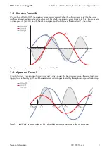
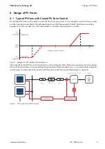
Figure 1: Pure active power: current and voltage are in phase

STP 12000TL-US-10 / 

STP 15000TL-US-10 / 

STP 20000TL-US-10 /

STP 24000TL-US-10 /

STP 30000TL-US-10

from firmware version 

2.80.00

from firmware version 

2.80.00

from firmware version  

2.80.00

Device type

Reactive power provision  

overexcited

 to 0 

underexcited

Q on Demand 24/7

Integrated Plant Control

Summary of Contents for STP 12000TL-US-10

Page 1: ...functions are available Device type Reactive power provision 0 overexcited to 0 underexcited Q on Demand 24 7 Integrated Plant Control STP 15000TL 10 STP 17000TL 10 from firmware version 2 60 02 from...

Page 2: ...er does not do any work and is therefore referred to as reactive power The time delay between the current and voltage curve its so called phase shift is a value which is easy to measure and characteri...

Page 3: ...n as pure reactive power Q unit Var from the French volt amp re r actif which moves back and forth in the cables Figure 2 Pure reactive power current and voltage are phase shifted by 90 1 3 Apparent P...

Page 4: ...compensated with Sunny Tripower inverters At the same time Sunny Tripower inverters can feed reactive power into the utility grid Compensation can take place both in feed in and non feed in operation...

Page 5: ...ansformers switching equipment etc has an influence on the characteristic curve of the PV power plant as a whole Figure 5 Example of a Q V specified by the grid operators This is why the central PV fa...

Page 6: ...ction point fast data transmission and installation and commissioning Grid friendly adherence to the characteristics desired by the grid operator even in the presence of very rapid changes in grid vol...

Page 7: ...length MV Transformer Nominal apparent power SN Impedance voltage vk Impedance loss in case of short circuit at nominal power Psc 3 2 Entering Key Values in Sunny Design You can find a detailed manua...

Page 8: ...rmer are activated in the area Configuration 10 Enter the key values for the cables used in the tabs Lines LV1 Lines LV2 and Lines LV3 11 In the tab MV transformer enter the key values for the MV tran...

Page 9: ...or software and log in as Installer or User 2 If required enter the SMA Grid Guard code 3 Select and set the required parameter 4 Save settings Parameter name for BLUETOOTH or Speedwire Webconnect Par...

Page 10: ...type and serial number PV system Impedance compensation Nominal apparent power of all inverters kVA Ohmic resistance for impedance compensation Lagging resistance for impedance compensation Leading r...

Page 11: ...ivate only the function Q on Demand 24 7 The general setting of the grid management service e g cos phi setpoint or Q V characteristic curve can be set independently of function Q on Demand 24 7 using...

Reviews: